Highly flexible couplings ELPEX series Siemens
Область применения
The ELPEX coupling is available in 9 sizes with a nominal torque of between 1600 Nm and 90000 Nm. The coupling is suitable for ambient temperatures of between –40 °C and +80 °C.
The ELPEX coupling is frequently used for high-quality drives which have to guarantee very long service life in harsh operating conditions. Examples of applications are mill drives in the cement industry, marine main and secondary drives or drives on large excavators powered by an electric motor or diesel engine.
Обзор
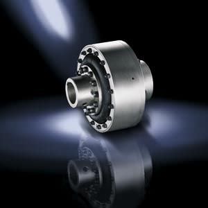
ELPEX couplings are highly torsionally flexible and free of torsional backlash. Because of their low torsional stiffness and damping capacity, ELPEX couplings are especially suitable for coupling machines with a very non uniform torque pattern. ELPEX couplings are also suitable for connecting machines with high shaft misalignment.
Standard ELPEX coupling types are designed as shaft-shaft connections or flange-shaft connections. Application-related types can be implemented on request.
Дизайн
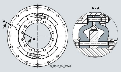
Design and function
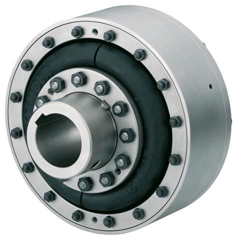
The ELPEX coupling''s transmission characteristic is determined essentially by the flexible rings. The flexible rings are manufactured from a natural rubber mixture with a multiply fabric lining. The flexible rings are split so that they can be changed without having to move the coupled machines.
The flexible rings are fastened to the hub with a clamping ring and to the outer flange with a clamping ring, using pins and bolts.
On the type EFG, the outer flange is designed with connection dimensions for connection to e.g. a diesel engine flywheel. On ENG types, the outer flange is fitted to a second hub part, which then enables the shaft-shaft connection.
Materials:
Type | ||
|---|---|---|
Cast iron | Steel | |
Hub part 1 | Grey cast iron | Steel |
Hub part 2 | Steel | Steel |
Retaining ring, outer ENG, ENGS | Grey cast iron | Steel |
Outer flange EFG, EFGS | Grey cast iron | Steel |
Flexible ring materials:
Material/description | Hardness | Identification | Ambient temperature |
|---|---|---|---|
Natural rubber | 70 ShoreA | Size - 2 | –40 °C to +80 °C |
ELPEX coupling types
Type | Description |
|---|---|
ENG | Coupling as shaft-shaft connection |
EFG | Coupling as flange-shaft connection |
ENGS | as ENG with fail-safe device |
EFGS | as EFG with fail-safe device |
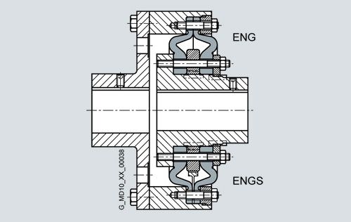
Types ENG/ENGS
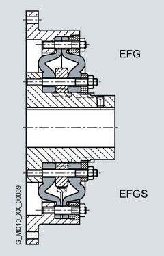
Types EFG/EFGS
Further application-specific coupling types are available.
Dimension sheets for and information on these are available on request. The following versions have already been implemented a number of times:
- ELPEX coupling with brake drum, brake disk or flywheel mass
- ELPEX coupling with axial backlash limiter
- ELPEX coupling with adapter
- ELPEX coupling in combination with a safety slip clutch
- ELPEX coupling for engaging/disengaging during standstill
- ELPEX coupling as part of a coupling combination
Fail-safe device of ELPEX coupling
Types ENGS and EFGS are provided with a fail-safe device. In normal operation the torsion angle of the flexible rings is smaller than the gap between the cams. In normal operation there is no metal-metal contact.
If the flexible rings fail, cams transmit the torque from the inner part and outer part. These enable the coupling to be used in emergency mode for a short time. This option is frequently required e.g. in the case of marine drives.
Fail-safe device
Конфигурация
The ELPEX coupling is especially suitable for rough operation. An application factor different from that in catalog section 3 is therefore sufficient for all applications. In the case of machines which excite torsional vibration, FLENDER urgently recommends carrying out a torsional vibration calculation or measuring the coupling load occurring in the drive.
Coupling selection
Coupling load in continuous operation
The operating principles of the driving and driven machines are divided into categories and the application factor FB derived from these in accordance with DIN 3990-1.
Application factor FB | Torque characteristic of the driven machine | ||
|---|---|---|---|
Torque characteristic of the driving machine | uniform with moderate shock loads | non uniform | very rough |
Electric motors, hydraulic motors, gas and water turbines | 1.0 | 1.3 | 1.4 |
Internal combustion engines | 1.3 | 1.4 | 1.6 |
Examples of torque characteristic in driven machines:
- uniform with moderate shock loads: generators, fans, blowers
- non uniform: reciprocating compressors, mixers,
conveyor systems - very rough: crushers, excavators, presses, mills
Temperature factor FT | Temperature Ta on the coupling | |||||
|---|---|---|---|---|---|---|
Coupling | Elastomer material | –40 °C to –30 °C | –30 °C to +50 °C | to 60 °C | to 70 °C | to 80 °C |
ELPEX | NR | 1.1 | 1.0 | 1.25 | 1.40 | 1.60 |
NR: Natural rubber mixture
Select size with: TKN ≥ TN · FB · FT
Coupling load at maximum and overload conditions
The maximum torque is the highest load acting on the coupling in normal operation.
Maximum torques at a frequency of up to 25 times an hour are permitted and must be lower than the maximum coupling torque. Examples of maximum torque conditions are: Starting operations, stopping operations or usual operating conditions with maximum load.
TKmax ≥ Tmax · FT
Overload torques are maximum loads which occur only in combination with special, infrequent operating conditions. Examples of overload torque conditions are: Motor short circuit, emergency stop or blocking because of component breakage. Overload torques at a frequency of once a month are permitted and must be lower than the maximum overload torque of the coupling. The overload condition may last only a short while, i.e. fractions of a second.
TKOL ≥ TOL · FT
Coupling load due to dynamic torque load
Applying the frequency factor FF, the dynamic torque load must be lower than the coupling fatigue torque.
Dynamic torque load
TKW ≥ TW · FT · FF · 0.6 / (FB – 1.0)
Frequency of the dynamic torque load
ferr ≤10 Hz frequency factor FF = 1.0
Frequency of the dynamic torque load
ferr >10 Hz frequency factor FF = √(ferr / 10 Hz)
Checking the maximum speed:
The following must apply to all load situations: nKmax ≥ nmax
Checking permitted shaft misalignment and restorative forces
For all load situations the actual shaft misalignment must be less than the permitted shaft misalignment.
Checking bore diameter, mounting geometry and coupling design
The check must be made on the basis of the dimension tables. On request, couplings with adapted geometry can be provided.
Checking shaft-hub connection
Please refer to catalog section 3 for instructions.
Checking temperature and chemically aggressive environment
The permitted coupling temperature is specified in the Temperature Factor FT table. In the case of chemically aggressive environments, please consult the manufacturer.
Особенности
The ELPEX coupling is suitable for horizontal and vertical mounting positions or mounting at any required angle. The coupling parts can be arranged as required on the shafts to be connected.
The split flexible rings can be changed without having to move the coupled machines.
The flexible rings are mounted without backlash and give the coupling progressive torsional stiffness, i.e. torsional stiffness increases in proportion to coupling load.
The ELPEX coupling is especially suitable for reversing operation or operation with changing directions of load.
The coupling is delivered preassembled. The flexible rings are completely assembled. On the type ENG, the coupling halves have to be bolted together after the hub has been mounted. On the type EFG, after mounting the coupling hub, only the outer flange has to be connected to the machine.
Outer flanges with different connection dimensions are available for the type EFG.
If the flexible rings are irreparably damaged or worn, the metal parts can rotate freely against one another, they are not in contact with one another.
Технические данные
Power ratings
Size | Rated torque | Maximum torque | Overload torque | Fatigue torque | Dynamic torsional stiffness for 100 % capacity utilization | Stiffness | Permitted shaft misalignment at speed | |||
|---|---|---|---|---|---|---|---|---|---|---|
Axial | Radial | Axial | Radial | Angle | ||||||
TKN | TKmax | TKOL | TKW | CTdyn | Ca | Cr | ΔKa | ΔKr | ΔKw | |
Nm | Nm | Nm | Nm | kNm/rad | N/mm | N/mm | mm | mm | Degree | |
270 | 1600 | 4800 | 6400 | 640 | 22.0 | 660 | 770 | 2.2 | 2.2 | 0.2 |
320 | 2800 | 8400 | 11200 | 1120 | 38.0 | 780 | 910 | 2.6 | 2.6 | 0.2 |
375 | 4500 | 13500 | 18000 | 1800 | 63.0 | 970 | 1130 | 3 | 3 | 0.2 |
430 | 7100 | 21300 | 28400 | 2840 | 97.0 | 1160 | 1350 | 3.4 | 3.4 | 0.2 |
500 | 11200 | 33600 | 44800 | 4480 | 155 | 1410 | 1630 | 3.8 | 3.8 | 0.2 |
590 | 18000 | 54000 | 72000 | 7200 | 240 | 1710 | 1990 | 4.2 | 4.2 | 0.2 |
690 | 28000 | 84000 | 112000 | 11200 | 365 | 2060 | 2390 | 4.6 | 4.6 | 0.2 |
840 | 45000 | 135000 | 180000 | 18000 | 685 | 2570 | 2990 | 5 | 5 | 0.2 |
970 | 90000 | 270000 | 360000 | 36000 | 1100 | 3020 | 3510 | 5.5 | 5.5 | 0.2 |
The damping coefficient is Ψ = 1.1
Torsional stiffness
The dynamic torsional stiffness is load-dependent and increases in proportion to capacity utilization. The values specified in the selection table apply to a capacity utilization of 100 %. The following table shows the correction factors for different rated loads.
CTdyn = CTdyn 100 % · FKC
Capacity utilization TN / TKN | |||||||
|---|---|---|---|---|---|---|---|
20 % | 50 % | 60 % | 70 % | 80 % | 100 % | 200 % | |
Correction factor FKC | 0.3 | 0.56 | 0.65 | 0.74 | 0.82 | 1 | 1.9 |
Torsional stiffness also depends on the ambient temperature and the frequency and amplitude of the torsional vibration excitation. More precise torsional stiffness and damping parameters on request.
Permitted shaft misalignment
The permitted shaft misalignment depends on the operating speed. As the speed increases, lower shaft misalignment values are permitted. The following table shows the correction factors for different speeds.
The maximum speed for the respective coupling size must be noted!
ΔKperm = ΔK1500 · FKV
Speed in rpm | ||||
|---|---|---|---|---|
500 | 1000 | 1500 | 3000 | |
Correction factor FKV | 1.6 | 1.25 | 1.0 | 0.70 |


 Ответ от производителя может занять до 5 дней и более.

