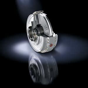
Non-positively acting couplings FLUDEX Siemens
Область применения
FLUDEX couplings are used in drives for conveyor systems such as belt conveyors, bucket elevators and chain conveyors. In heavy industry FLUDEX couplings are used for applications such as blade wheel drives, crushers, roller presses, mixers, large ventilators, boiler feed pumps, large compressors, centrifuges and auxiliary drives for mills.
Further applications are, for example, pump drives, PTO generator drives, windpower systems and door and gate drives.
In drives with diesel engine FLUDEX couplings are used on driven machines with a high mass moment of inertia.
Обзор

Coupling suitable for potentially explosive environments. Complies with Directive 94/9/EC for:


II 2 Gc T3 D160 °C II B
–30 °C ≤ Ta ≤ +50 °C
I M2
For Ex zones 2 and 2Z, device category 3 is available upon request:
II 3 Gc T4 D120 °C II B
FLUDEX couplings marked with Ex are constructed with fusible safety plugs 110 °C.
Дизайн
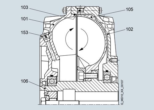
FLUDEX couplings are constructed of just a few, robust components. Internal components include the hollow shaft or solid shaft (106), to which the blade wheel (105) is connected. The outer housing comprises the cover (102) and the blade wheel housing (101). The joint is constructed as a bolted flange joint and sealed with an O ring. The outer housing and the shaft or hollow shaft have double bearing support and are sealed off to the outside with radial shaft seals. The coupling is provided with two filler plugs (153) with integral overflow protection and with one or two fusible safety plugs (103) in the coupling housing for protection against overheating. The fusible safety plug or a screw plug fitted in the same position also serves as a fluid drain plug and with the aid of a scale marking on the housing can be used as a level indicator.
Materials
Blade wheel and housing
Cast aluminum AlSi10Mg
Shaft and hollow shaft
Steel with a yield point higher than 400 N/mm2
Static seals and radial shaft seals
Perbunan NBR or Viton FPM
Add-on parts
Grey cast iron EN-GJL-250, spheroidal graphite cast iron EN-GJS-400 or steel with a yield point higher than 400 N/mm2
Fusible safety plugs
If a FLUDEX coupling is operated with an impermissibly high slip for a prolonged period, the oil filling and the coupling housing will overheat. Fusible safety plugs which release the oil filling into the environment upon reaching a preset temperature are therefore fitted in each coupling housing. These protect the coupling from irreparable damage through overheating or overpressure and disconnect the drive motor from the driven machine.
Thermal equipment
Equipment | Suitability | Fusible safety plug | Sealing material | Additional |
|---|---|---|---|---|
1 | 110 °C | NBR | F01 | |
FPM | F05 | |||
Standard | 1 | 140 °C | NBR | – |
1 | 140 °C | FPM | F07 | |
2 | 160 °C | FPM | F08 | |
ATEX | 1 | 110 °C ex | NBR | F02 |
FPM | F06 | |||
With thermal switch1) | 1 | 140 °C + thermal switch 110 °C | NBR | F03 |
FPM | F10 | |||
2 | 160 °C + thermal switch 140 °C | FPM | F11 | |
With transmitter1) | 2 | 160 °C + EOC transmitter (125 °C) | NBR | F04 |
FPM | F12 | |||
Incl. switchgear | F25 | |||
Incl. sensor and evaluation instrument | F26 |
1) Not available for size 222.
Suitability:
1 = suitable for continuous coupling operation temperatures up to 85 °C
2 = suitable for continuous coupling operation temperatures up to 110 °C
The switchgear or sensor and evaluation instrument for the EOC system must be ordered separately, using the product code.
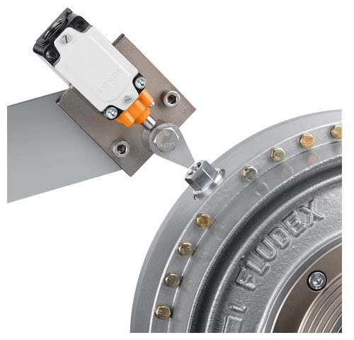
Thermal switching equipment
By adding thermal switching equipment leakage and loss of the hydraulic fluid as well as a risk to and contamination of the environment in the event that the coupling overheats can be avoided.
The thermal switching equipment does not work if a machine side is blocked and the coupling housing is connected to this side. If the coupling is stationary, the switching pin cannot actuate the switching equipment.
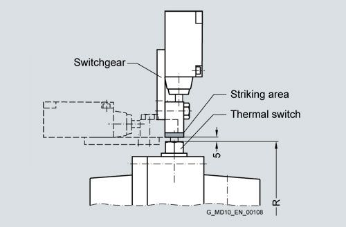
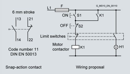
The thermal switching equipment comprises the thermal switch and the switchgear.
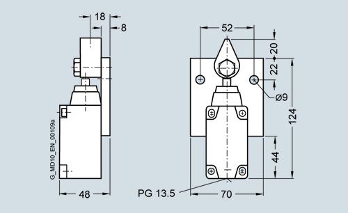
The switchgear comprises a limit switch with a make-and-break contact and a swiveling cam. Limit switch and cam are mounted on a common base plate. The thermal switch is screwed into the housing in place of a screw plug. The fusible safety plug (with a higher response temperature) remains in the coupling for additional safety.
If the set temperature is exceeded, the switching pin is released from the fusible element, emerges 10 mm from the housing and actuates the switchgear while the coupling is rotating. The switchgear can cut out the drive motor and/or trigger an optical or acoustic alarm signal.
The housing of the coupling remains closed and no operating fluid will escape.
Assignment
Continuous operating temperature | Thermal switch | Fusible safety plug |
|---|---|---|
≤85 °C | 110 °C | 140 °C |
>85 ° … ≤110 °C | 140 °C | 160 °C |
Size | |||||||||||||
|---|---|---|---|---|---|---|---|---|---|---|---|---|---|
297 | 342 | 370 | 395 | 425 | 450 | 490 | 516 | 565 | 590 | 655 | 755 | 887 | |
Perm. speed in rpm | 2500 | 2240 | 2100 | 2000 | 1900 | 1800 | 1650 | 1600 | 1500 | 1450 | 1250 | 1100 | 1000 |
Radius of travel R in mm | 188 | 215 | 226 | 239 | 251 | 271 | 292 | 307 | 330 | 346 | 383 | 435 | 507 |
From coupling size 297, the thermal switching equipment can be used up to a peripheral speed of 50 m/s. At higher speeds, an EOC system should be provided.
Switchgear: FFA 000000652020
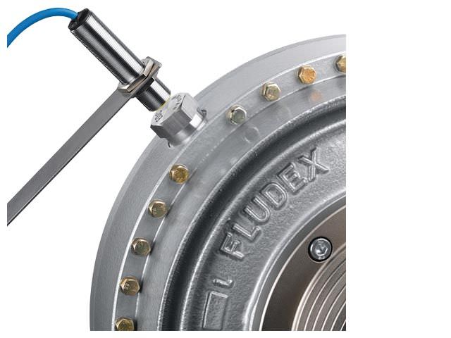
EOC system
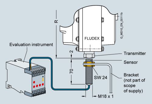
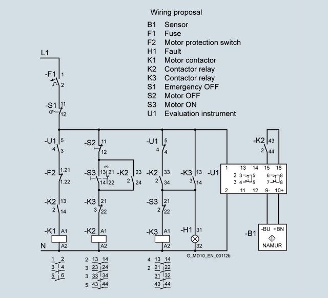
On the EOC system the temperature-dependent magnitude of the magnetic field of the EOC transmitter is measured and used for a switching pulse. The transmitter signal is transmitted via the fixed sensor to the evaluation instrument and there compared with the set value. If the signal does not exceed the minimum value or no signal is received, the relay of the evaluation instrument switches over. This can cause a malfunction message to be sent and the motor cut out. The coupling housing remains closed. The fusible safety plug with a higher response temperature remains in the coupling for additional safety.
The response temperature of the EOC system is 125 °C.
Components of the EOC system
Component | Product code |
|---|---|
EOC transmitter with seal | FFA 000001194899 |
Sensor EOC | FFA 000000361460 |
Evaluation instrument EWD | FFA 000001205294 |
Radius of travel R to the transmitter
Size | |||||||||||||
|---|---|---|---|---|---|---|---|---|---|---|---|---|---|
297 | 342 | 370 | 395 | 425 | 450 | 490 | 516 | 565 | 590 | 655 | 755 | 887 | |
R in mm | 188 | 215 | 226 | 239 | 251 | 271 | 292 | 346 | 330 | 346 | 383 | 435 | 507 |
Функции
Föttinger principle
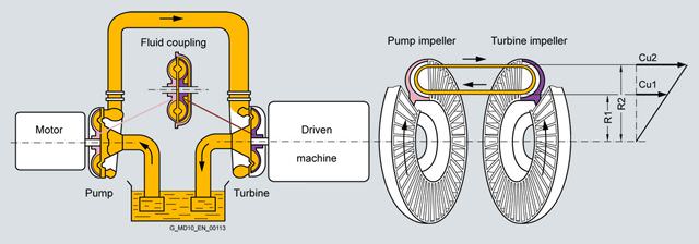
Two opposing, radially bladed impellers are housed in a leakproof housing. The impellers are not mechanically connected to each other. Because of the axially parallel arranged blades, the torque is transmitted independently of the direction of rotation and solely by the oil filling.
Hydrodynamic couplings have the characteristic properties of fluid flow engines. The transmissible torque depends on the density and quantity of the operating fluid and increases as the square of the drive speed and the fifth power of the profile diameter denoting the coupling size. In the driven pump impeller, mechanical energy is converted into kinetic flow energy of the operating fluid. In the turbine impeller, which is connected to the output side, flow energy is converted back to mechanical energy.
To generate the operating fluid circulation necessary for torque transmission, a difference in speed is necessary between the pump and turbine impellers. A centrifugal force pressure field is set up that is greater in the faster rotating pump impeller than in the turbine impeller. The difference in speed, usually termed “slip”, at the continuous operating point of the coupling is between 2 % and 6 %, depending on application and coupling size. Immediately after drive motor start-up slip is 100 %, i.e. the pump impeller is driven at the speed of the motor, but the turbine impeller remains stationary.
Slip multiplied by the transmitted power represents the power loss of the coupling, which is converted into heat inside the oil filling. The amount of heat generated must be released into the environment via the coupling housing to prevent an impermissible temperature rise. The rated coupling output is mainly determined by the power loss which can be dissipated at a still acceptable operating temperature or a reasonable set slip limit. This distinguishes the FLUDEX coupling from all positively acting coupling assembly options for which the rated coupling torque is the defining characteristic.
Depending on the FLUDEX coupling series, drive is via the inner rotor (shaft/hollow shaft with rigidly connected blade wheel) or via the bladed housing impeller (blade wheel housing). The driving impeller is the pump impeller, and the driven impeller is the turbine impeller.
A low-viscosity mineral oil VG 22/VG 32, which also serves to lubricate the bearings, is used as fluid. In special types water, a water emulsion or low-flammability fluid may be used as a non-combustible fluid.
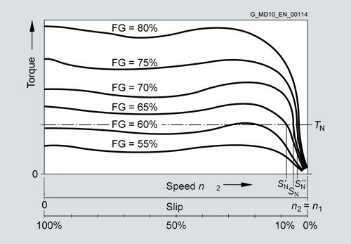
Slip-torque characteristics for different filling levels FG
The torque characteristic depends on the oil filling quantity FG in the coupling. This enables the transmissible torque on starting up to be set via the filling level. With a higher filling level the starting torque increases, while the operating slip and thus the coupling temperature rise decreases.
Conversely, with a lower filling level the starting torque decreases, the coupling becomes softer, while slip and coupling temperature rise.
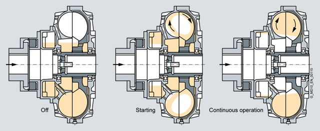
Operation of the delay chamber
Starting torque can be reduced without increasing continuous operating slip by using a type of coupling with a delay chamber. On these couplings part of the oil filling is initially stored inactively in the delay chamber. The starting torque is considerably reduced because of the thus reduced starting filling in the working chamber of the coupling. The filling in the delay chamber runs very slowly, mostly only at the finish of the starting operation, from the delay chamber into the working chamber, causing the active filling in it to rise gradually and the continuous operating slip to reach a value corresponding to the whole filling.
Конфигурация
Selection of FLUDEX coupling
In accordance with the requirements catalog various series, sizes and types of FLUDEX coupling are available. The FLUDEX coupling series is characterized by various flow chamber configurations, fitted delay chambers or fittings in the flow chamber. The types are determined by the design of the add-on coupling. This results in different starting factors and characteristics which can be used for the most varied applications. The size is specified by stating the flow outside diameter.
When selecting, the series required for the application, taking into account the starting factor and the characteristic, must be selected.
Selection of FLUDEX series
FLUDEX couplings which are to be used without special conditions solely as an aid to starting the motor can be selected using the assignment tables on page 13/12 (for n = 1500 rpm) or on page 13/14 (for n = 3000 rpm).
If special requirements, based on the operating method of the prime mover or driven machine, are made of the coupling or the coupling is to be used in extreme environmental conditions, please give specific details in the enquiry or order. The form “Technical specifications for the selection of type and size” can be used for this purpose.
Description of the FLUDEX series
FA series – drive via the hollow shaft (impeller drive)
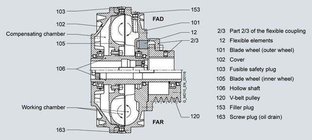
FLUDEX FA series couplings are basic couplings (without delay chamber) which are driven via the hollow shaft (106) with attached blade wheel (105). This enables the advantages of the compensating chamber and the working chamber to be used to best effect. Combinations with brake drums/disks and pulleys can also be easily achieved. When the coupling is started, part of the oil filling in the area of greatest slip is forced into the radially inner chambers and the compensating chamber by the strong rotational flow. This causes the effective oil filling in the working chamber to be reduced and the desired torque limitation (approx. twice TN) to be achieved during starting. By means of additional fittings the coupling torque at the start of the starting operation can be limited to approx. 1.5 times of the rated value. During run-up to speed the compensating chamber again empties into the working chamber, and this helps to reduce slip.
FG and FV series – drive via the housing
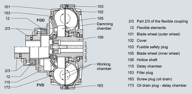
FLUDEX FG and FV series couplings are designed for drive via the coupling housing. In the FV series (coupling with delay chamber), the motor drives the coupling housing, comprising a blade wheel (101) and a cover (102), via the flexible N-EUPEX coupling (part 2/3) and the delay chamber (115). The rotational flow of the coupling filling drives the blade wheel (105) and the hollow shaft (106) on the output side, which is mounted on the gear unit or driven machine shaft. In the FG series (basic coupling), there is no delay chamber, and the flexible coupling is directly flange-mounted on the blade wheel.
When the coupling is started up, part of the oil filling is forced into the damming chamber. This enables the desired torque limitation (approx. twice TN) to be achieved during starting. In the FV series the delay chamber also receives part of the oil filling in accordance with the fluid level when the coupling is stationary. During starting the effective oil filling in the working chamber is reduced by the amount of fluid in the delay chamber, thus considerably reducing the starting torque (approx. 1.5 times TN). From the delay chamber located on the drive side, the oil is fed back time-dependently to the working chamber via small holes and the coupling torque is raised, even if the output is blocked.
This replenishing function enables a drive to be soft-started with a very low starting torque and with an almost load-free motor. At the same time, however, increased load torques can be overcome by the torque increase in the coupling.
The property of the coupling with delay chamber can be used advantageously, for example, to soft-start empty, partly loaded and fully loaded conveyor belts.
FG series couplings are used for normal starting torque limitation, as a starting clutch for isolating vibration and for overload limitation in the event of drive blockage.
FN series – drive via housing
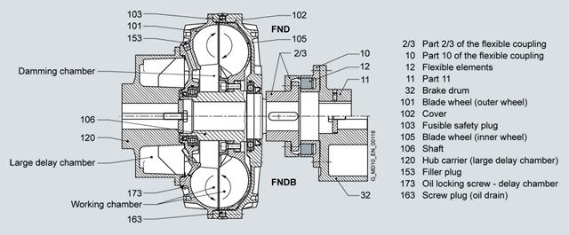
FLUDEX FN series couplings have a larger delay chamber than the FV series. The delay chamber is designed as a hub carrier (120) and is mounted on the motor shaft. The hub carrier is flange-fitted to the housing (101, 102) of the FLUDEX coupling. Output is via the blade wheel (105) and the shaft (106) to the flexible N-EUPEX coupling connecting to the gear unit or driven machine. With types FND, FNDB and FNDS the coupling can be dismounted radially without moving the coupled machines.
Because of the larger delay chamber, FN couplings enable even softer starting than FV couplings. Torque limitation during starting is approx. 1.3 times TN. A further advantage of types FNDB and FNDS is the favorable weight distribution.
The normally stronger motor shaft bears the weight of the hub carrier (cast version) and the main coupling. The gear unit shaft carries only the brake drum or disk and the output-side part of the flexible coupling. At the same time, the principle of the drive-side delay chamber with the capacity for increasing torque time-dependently is retained. FN couplings have the same fields of application as FV couplings. However, they offer special advantages in the brake disk design because of the weight distribution.
Depending on the series selected, different starting characteristics arise during starting.
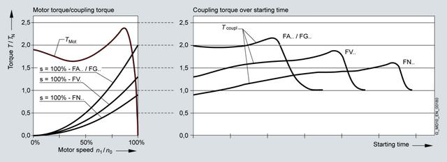
FLUDEX series:
Series | Description |
FA../FG.. | Basic coupling without delay chamber |
FV.. | Coupling with delay chamber |
FN.. | Coupling with large delay chamber |
Selection of FLUDEX type
Listed in the catalog are FLUDEX couplings with pulley, brake drum, brake disk and flexible N-EUPEX coupling.
Further types, e.g. in combination with a torsionally rigid steel membrane coupling of the ARPEX series or a highly flexible coupling of the ELPEX or ELPEX-S series, are available.
Series | Type | Add-on coupling | Characteristic feature |
|---|---|---|---|
FA
| FAO | Without | Basic coupling with connecting flange |
FAR | Without | with attached pulley | |
FAD | N-EUPEX D | 1) | |
FAE | N-EUPEX E | enables larger bores on the output side | |
FAM | N-EUPEX M | enables a short fitting length | |
FADB | N-EUPEX D | with brake drum | |
FADS SB | N-EUPEX D | 1) with brake disk for stopping brakes | |
FADS HB | N-EUPEX D | 1) with brake disk for blocking brakes | |
FG
| FGO | Without | Basic coupling with connecting flange |
FGD | N-EUPEX D | 1) | |
FGE | N-EUPEX E | enables larger bores on the output side | |
FGM | N-EUPEX M | enables a short fitting length | |
FV
| FVO | Without | Coupling with connecting flange |
FVD | N-EUPEX D | 1) | |
FVE | N-EUPEX E | enables larger bores on the output side | |
FVM | N-EUPEX M | enables a short fitting length | |
FN
| FNO | Without | Coupling with connecting shaft |
FNA | N-EUPEX A | 1) enables a short fitting length | |
FND | N-EUPEX D | 1)2) | |
FNDB | N-EUPEX D | 1)2) with brake drum | |
FNDS SB | N-EUPEX D | 1)2) with brake disk for stopping brakes | |
FNDS HB | N-EUPEX D | 1)2) with brake disk for stopping brakes |
1) Enables change of flexible elements without moving the machines axially.
2) Enables the coupling to be fitted or dismounted without displacing the coupled machines.
The maximum shaft displacements permissible for an N-EUPEX add-on coupling are shown in catalog section 7. For greater shaft displacements FLUDEX couplings can be combined with cardan shafts or other displacement couplings.
Selection of FLUDEX size
The FLUDEX size is determined by the output to be transmitted in comparison with the rated outputs listed in the following tables. No application factors or additional safety factors need be taken into consideration. The rated outputs stated in the tables normally require the maximum permissible filling (80 % bis 85 %) of the coupling and because of operating slip, lead to the coupling heating up by approx. 50 °C relative to the ambient (cooling air) temperature. With lower outputs, coupling heating will be proportionately lower. If for continuous operation of the coupling an absolute temperature (ambient temperature + coupling heating) of >85 °C is expected, the coupling must be fitted with FPM seals and 160 °C fusible safety plugs.
FA series
Speed in rpm | ||||||||||||||
|---|---|---|---|---|---|---|---|---|---|---|---|---|---|---|
600 | 740 | 890 | 980 | 1180 | 1350 | 1470 | 1600 | 1770 | 2000 | 2300 | 2600 | 2950 | 3550 | |
Rated output PN in kW | Size | |||||||||||||
1,2 | 1,6 | 2,8 | 4,2 | 5,5 | 6,9 | 8,7 | 11,7 | 15 | 19 | 24 | 33 | 222 | ||
1,2 | 2,3 | 4 | 5,5 | 9 | 14 | 18,5 | 23 | 29 | 37 | 48 | 60 | 70 | 90 | 297 |
2,6 | 4,8 | 8,7 | 11,5 | 18 | 27 | 34 | 40 | 51 | 65 | 82 | 97 | 120 | 145 | 342 |
5,7 | 10 | 16 | 21 | 36 | 49 | 61 | 74 | 87 | 105 | 135 | 165 | 180 | 395 | |
11 | 21 | 32 | 41 | 65 | 90 | 110 | 127 | 155 | 190 | 230 | 290 | 370 | 450 | |
19 | 36 | 60 | 75 | 115 | 154 | 190 | 215 | 260 | 310 | 395 | 516 | |||
37 | 69 | 109 | 134 | 200 | 260 | 320 | 360 | 435 | 540 | 590 | ||||
FG, FV and FN series
Speed in rpm | ||||||||||||||
|---|---|---|---|---|---|---|---|---|---|---|---|---|---|---|
600 | 740 | 890 | 980 | 1180 | 1350 | 1470 | 1600 | 1770 | 2000 | 2300 | 2600 | 2950 | 3550 | |
Rated output PN in kW | Size | |||||||||||||
4 | 7,5 | 12 | 16 | 26 | 38 | 48 | 61 | 85 | 110 | 140 | 170 | 220 | 290 | 370 |
7,5 | 15 | 23 | 30 | 48 | 70 | 90 | 115 | 140 | 175 | 220 | 280 | 340 | 425 | |
15 | 30 | 45 | 58 | 95 | 140 | 180 | 210 | 245 | 300 | 380 | 480 | 490 | ||
28 | 55 | 85 | 110 | 180 | 255 | 300 | 350 | 420 | 525 | 660 | 565 | |||
55 | 110 | 170 | 220 | 350 | 450 | 520 | 600 | 730 | 900 | 655 | ||||
110 | 210 | 330 | 440 | 600 | 760 | 870 | 1010 | 1220 | 755 | |||||
240 | 440 | 700 | 810 | 1130 | 1440 | 1660 | 887 | |||||||
480 | 880 | 1400 | 1600 | 2000 | 2350 | 2500 | 887D1) | |||||||
1) D = double-flow variant on request.
Особенности
FLUDEX couplings are hydrodynamic fluid couplings which operate on the Föttinger principle. The coupling parts on the input and output sides are not mechanically connected to each other. Output is transmitted via the oil filling which rotates in the coupling and is conducted over radially arranged blades.
FLUDEX couplings limit starting and maximum torque in the drive train and, through the property of rotational slip, serve as an aid to starting the motor, as overload protection in the event of fault and for isolating torsional vibration.
When large masses are started up, the drive train is accelerated only at the torque determined by the coupling characteristic. The starting operation is spread over time, the driven machine started softly and smoothly.
In the case of special operating conditions, such as overload or blocking of the driven machine, the FLUDEX coupling limits the maximum torque load and prevents the inert effect of the rotating motor mass on the drive train.
The coupling then acts as a load-holding safety clutch until the drive is shut off by the motor control or coupling monitoring system.
The FLUDEX coupling further acts as a means of decoupling during torsional vibration excitation. Torsional vibration excitation with a frequency of > 5 Hz is virtually absorbed by the coupling.
To compensate for shaft misalignment, the FLUDEX coupling is combined with a displacement coupling e. g. of the N-EUPEX type.
All FLUDEX couplings are designed with radial unset blades and are therefore suitable for rotation in both directions and reversing operation. They can be fitted horizontally, at an angle or vertically. In the case of FLUDEX couplings with a delay chamber it must be ensured, when fitting at an angle or vertically, that the delay chamber is below the working chamber.
Технические данные
Balancing FLUDEX couplings
In deviation from the balancing specifications in catalog section 2, all FLUDEX couplings complying with DIN ISO 1940 are balanced to balancing quality G6.3 for 1800 rpm. For operating speeds higher than 1800 rpm micro-balancing, based on operating speed, can be requested (order code +W03 required).
Balancing is a two-level balancing with the specified oil quantity or a 75 % filling.
FLUDEX couplings are balanced in accordance with the half parallel key standard. Other balancing standards must be specified in the order, using the product code key (see catalog section 2).
Add-on couplings are subject to the standards as set out in catalog section 2.
Oil filling
FLUDEX couplings can be delivered with or without oil filling.
- Delivery without oil filling:
without order code - Delivery with oil filling:
product code with -Z and order code F16 and Y90 with plain text specification of the oil filling quantity in liters. - Delivery without oil filling but with oil filling quantity specification: Product code with -Z and order code Y90 with plain text specification of the oil filling quantity in liters.
Hollow shafts of the FA, FG and FV series
Variant of FLUDEX hollow shafts only with finished bore:
Order code for bore diameter is required.
Operating temperature range of FLUDEX couplings
FLUDEX couplings are suitable for ambient temperatures of between -40 °C and +40 °C. For use at temperatures below -15 °C, FLUDEX couplings are generally delivered without oil filling. For the selection of the operating oil for low temperatures, attention must be paid to a sufficient low freezing point of the oil and his compatibility to sealing elements. The temperature limits of the N-EUPEX add-on coupling are shown in part 7 of this cataloge. If other displacement coupling are combinded with a FLUDEX coupling, their respective temperature limits must be taken into account.
Operating conditions for FLUDEX couplings in potentially explosive environments
The coupling with fusible safety plugs with identity marking
T3 is suitable for the operating conditions set out in Directive 94/9/EC:
- Equipment group II (above-ground applications) temperature class T3 of categories 2 and 3 for environments where there are potentially explosive gas, vapors, mist and air mixtures and for environments where dust can form potentially explosive atmospheres.
- Equipment group I (below-ground applications) of category M2
If used in potentially explosive environments under ground, aluminum couplings must be provided with a robust enclosure to preclude the risk of ignition caused by e.g. friction, impact or friction sparks. The deposit of heavy-metal oxides (rust) on the coupling housing must be prevented by the enclosure or other suitable means.
FLUDEX couplings can be delivered with fitted brake disk or V-belt pulley. Designing the belt drive or the brake disk to conform with the guidelines is the responsibility of the subassembly supplier. It should be noted that there is a risk from, amongst other things, electrostatic charges and hot surfaces. Under BGR 132 (regulations of German Institute for Occupational Safety) the use of V-belts in conjunction with IIC gases is not permitted.
Axial retention
Axial retention is provided by a set screw or end washer with a retaining screw for shaft ends to DIN 748/1 with a centering thread to DIN 332/2. Other methods must be specified in the order, using the product code with -Z and order code Y99 with plain text specification, unless ordering options are available.
Bore and keyway width tolerances are specified in catalog section 15.
Weights specified in the dimension order tables apply to maximum bore diameters without oil filling.


 Ответ от производителя может занять до 5 дней и более.

