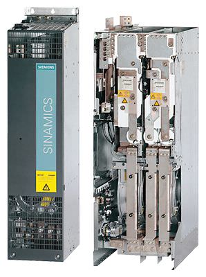
SINAMICS S120 Chassis Format Units Siemens

Обзор
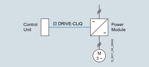
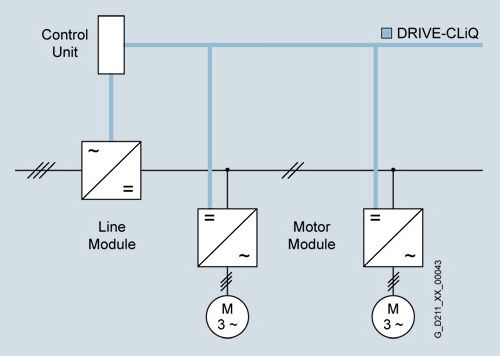
With its separate power unit and control module (Control Unit), the SINAMICS S120 drive system can be perfectly adapted to a wide variety of different drive tasks.
The control module is selected according to the number of drives to be controlled and the required performance level, while the power unit must be rated to meet requirements regarding regenerative feedback capability or energy exchange. The connection between the Control Unit and power unit is made very simply using the digital system interface DRIVE-CLiQ.
The following drive units are available in the chassis format:
- Power Modules
- Basic Line Modules
- Smart Line Modules (only available in the air-cooled version)
- Active Line Modules
- Active Interface Modules (only available in the air-cooled version)
- Motor Modules
Power Modules
The simplest variant of a SINAMICS S120 drive system comprises a CU310 Control Unit and a Power Module. In Power Modules specifically designed for single drives without regenerative feedback into the line supply, the line-side infeed and the motor-side power unit are combined in one unit.
Generated energy produced during braking is converted to heat via braking resistors.
The Control Unit is plugged onto the Power Module; in addition to the complete control intelligence, the Control Unit also has all the drive interfaces for communication with higher-level systems and interfacing of add-on components.
Line Modules
Line Modules contain the central line infeed for the DC link. Various Line Modules can be selected to address the various application profiles:
- Basic Line Modules
- Smart Line Modules
- Active Line Modules
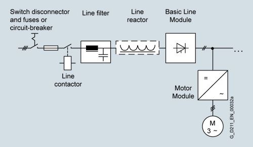
Basic Line Modules
Basic Line Modules are designed only for infeed operation, i.e. they are not capable of recovering energy to the mains supply. If regenerative energy is produced, e.g. when drives brake, it must be converted to heat by means of a Braking Module and a braking resistor.
A line filter can be optionally installed in order to maintain the limit values according to EN 61800-3, Class C2.
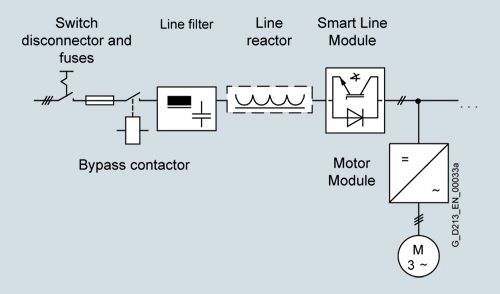
Smart Line Modules
Smart Line Modules can supply energy and recover energy to the mains supply. Braking Module and braking resistor are only required, if, also for a power failure – without energy recovery option – it is necessary to brake the drives in a controlled fashion. When a Smart Line Module is used as the infeed, the matching line reactor must be installed.
Active Line Modules
Active Line Modules can supply energy and return regenerative energy to the supply system. Braking Module and braking resistor are only required, if, also for a power failure – without energy recovery option – it is necessary to brake the drives in a controlled fashion.
Contrary to the Basic Line Modules and Smart Line Modules, Active Line Modules generate a controlled DC voltage. This is kept constant, independent of any line voltage fluctuations, assuming that the line voltage fluctuates within the permitted tolerances. Active Line Modules draw a virtually sinusoidal current from the supply which limits any harmful harmonics. All the components required to operate an Active Line Module are integrated in the Active Interface Module.

Motor Modules
A voltage DC link and an inverter for supplying a motor are integrated in the Motor Module.
Motor Modules are designed for multi-axis drive systems and are controlled by either a CU320-2 or a SIMOTION D Control Unit. Motor Modules are interconnected through a common DC bus.
One or several Motor Modules are supplied with energy for the motors via the DC link. Both synchronous and induction motors can be operated.
Since the Motor Modules share the same DC link, they can exchange energy with one another, i.e. if one Motor Module operating in generator mode produces energy, the energy can be used by another Motor Module operating in motor mode. The DC link is supplied with line supply voltage by a Line Module.
Control Units
The control intelligence for all the drive axes integrated in the multi-axis group is combined in the Control Units. They also feature drive-related inputs/outputs and interfaces for communicating with higher-level controllers. Control Units are available with different ranges of functions and with different performance levels.
System components
The structure of the drive system is defined by selecting the Control Unit and Power Module or Line Module and Motor Modules. The additional components provided allow optimum adaptation of the drive system to the application.
These components are subdivided into:
- Line-side components, e.g. line reactors and line filters
- DC link components, e.g. Braking Modules and braking resistors
- Motor-side components, e.g. motor reactors and dv/dt filters plus VPL, sine-wave filters
- Supplementary system components, e.g. Terminal Modules, operator panels and Communication Boards
- Encoder system interface for connecting various types of encoders to SINAMICS S120
DRIVE-CLiQ system interface
All SINAMICS S120 components are equipped with the highperformance DRIVE-CLiQ system interface.
Line and Motor Modules are connected to the Control Unit and Terminal and Sensor Modules to the drive system via DRIVECLiQ – simply and efficiently. Motors that also have this interface can be directly connected to the drive system.
Varnished PCBs
The following drive units are equipped as standard with varnished PCBs:
- Blocksize format units
- Booksize format units
- Chassis format units
- Control Units
- Sensor Modules
- Terminal Modules
- Advanced Operator Panel (AOP30)
The varnish coating on the modules protects the sensitive SMD components against corrosive gases, chemically active dust and moisture.
Nickel-plated busbars
All of the copper busbars used are nickel-plated in order to achieve the best possible immunity to environmental effects. Further, the bare copper connections do not have to be cleaned for customer connections.
Функции
Communication with higher-level control and customer terminal block
As customer interface to a higher-level control, as standard there is a PROFIBUS or PROFINET communication interface on the CU320-2 Control Unit; there are also expansions such as the TM31 Terminal Module, the TB30 Terminal Board and modules to support CANopen.
This customer terminal block can be used to connect the system to the higher-level controller using analog and digital signals, or to connect additional units.
For additional information, please refer to the SINAMICS Low Voltage Engineering Manual on the CD-ROM provided with the catalog.
Open-loop and closed-loop control functions
SINAMICS S120 has a high-dynamic vector control with speed and current control – with and without speed actual value feedback.
Software and protective functions
The software functions available as standard are described below:
Software and protective functions | Description |
|---|---|
Setpoint input | The setpoint can be input both internally and externally. It is applied internally as a fixed setpoint, motorized potentiometer setpoint or jog setpoint, and externally via the communications interface or an analog input – when using the TB30 Terminal Board or the TM 31 Terminal Module. The internal fixed setpoint and the motorized potentiometer setpoint can be switched over or adjusted using control commands from any interface. |
Motor identification | The automatic motor identification function makes commissioning faster and easier and optimizes closed-loop control of the drive. |
Ramp-function generator | A user-friendly ramp-function generator with separately adjustable ramp-up and ramp-down times, together with adjustable rounding times in the lower and upper speed ranges, allows the drive to be smoothly accelerated and braked. This results in a good speed control response and plays its role in reducing the stress on the mechanical system. The down ramp can be parameterized separately for a quick stop. |
Vdc max controller | The Vdc max controller automatically prevents overvoltages in the DC link if the down ramp is too short, for example. This may also extend the set ramp-down time. Comment: This function only makes sense for single-axis applications. |
Kinetic buffering (KIP) | For brief line supply failures, the kinetic energy of the rotating drive is used to buffer the DC link and therefore prevents fault trips. The drive converter remains operational as long as the drive can provide regenerative energy as a result of its motion and the DC link voltage does not drop below the shutdown threshold. When the line supply recovers within this time, the drive is again bumplessly accelerated up to its setpoint speed. |
Automatic restart | The automatic restart switches the drive on again when the power is restored after a power failure, and ramps up to the current speed setpoint. |
Flying restart | The flying restart function allows the converter to be switched to a motor that is still turning. |
Technology controller | Using the technology controller (PID controller) function module, level or flow controls and complex tension controls can be implemented, for example. The existing D component can act both on the system deviation as well as on the actual value (factory setting). The P, I, and D components are separately set. |
Free function blocks | Using the freely programmable function blocks, it is easy to implement logic and arithmetic functions for controlling the SINAMICS drive. The blocks can be programmed by means of an operator panel or the STARTER commissioning tool. |
Drive Control Chart (DCC) | Drive Control Chart (DCC) is an additional tool for the easy configuration of technological functions for SINAMICS. The block library contains a large selection of control, arithmetic and logic blocks as well as extensive open-loop and closedloop control functions. The user-friendly DCC Editor enables easy graphics-based configuration, allows control loop structures to be clearly represented and provides a high degree of reusability of diagrams that have already been created. DCC is an add-on to the STARTER commissioning tool (→ Tools and engineering). |
I2t detection for motor protection | A motor model stored in the converter software calculates the motor temperature based on the current speed and load More exact sensing of the temperature, which also takes into account the influence of the ambient temperature, is possible by means of direct temperature sensing using KTY84 sensors in the motor winding. |
Motor temperature evaluation | Motor protection by evaluating a KTY84, PTC or Pt100 temperature sensor. When a KTY84 temperature sensor is connected, the limit values can be set for alarm or shutdown. When a PTC thermistor is connected, the system reaction to triggering of the thermistor (alarm or shutdown) can be defined. |
Motor blocking protection | A blocked motor is detected and protected against thermal overloading by a fault trip. |
Power unit protection
Power unit protection | Description |
|---|---|
Ground fault monitoring at the output | A ground fault at the output end is detected by an aggregate current monitor and results in shutdown in grounded-neutral systems. |
Electronic short-circuit protection at the output | A short-circuit at the output (e.g. at the converter output terminals, in the motor cable or in the motor terminal box) is detected and the converter shuts down with a "fault". |
Thermal overload protection | An alarm is issued first when the overtemperature threshold responds. If the temperature continues to rise, the unit either shuts down or independently adjusts the pulse frequency or output current so that thermal load is reduced. Once the cause of the fault has been eliminated (e.g. cooling has been improved), the original operating values are automatically resumed. |
Safety Integrated functions
The integrated safety functions of SINAMICS provide highlyeffective application-oriented protection for personnel and machinery. The Safety Integrated functions are implemented electronically and therefore offer short response times in comparison to solutions with externally implemented monitoring functions.
The trend toward greater complexity and increasing modularity of machines is increasingly seeing a shift in safety functions away from the classical central safety functions (for example, shutdown of the complete machine using a main switch) and into the machine control system and the drives. Frequently, this also significantly increases the productivity. This is because, for instance, equipping times can be reduced and during these equipping times, depending on the machine type, other parts can still continue to produce.
Integrated safety functions act much faster than those of a conventional design. The safety of a machine is increased further with Safety Integrated. Furthermore, thanks to the faster method of operation, safety measures controlled by integrated safety systems are perceived as less of a hindrance by the machine operator, therefore significantly reducing the motivation to consciously bypass safety functions.
The safety functions in the device and communication via PROFIsafe have already been certified. This simplifies configuring the safety functions and especially the acceptance of the plant or system by an authorized testing body when compared to safety solutions made up of individual safety components.
Legal framework
Machine and plant builders must ensure that their machines or plants neither present risks due to electric shock, heat or radiation nor due to functional faults. In Europe, for example, compliance with the machinery directive is legally stipulated by the EU industrial safety directive.
In order to ensure compliance with this directive, it is recommended that the corresponding harmonized European standards are applied. This initiates the assumption of conformity and gives manufacturers and operators the legal security when complying with both national regulations and EU directives. The machine manufacturer uses the CE marking to document the compliance with all relevant directives and regulations in the free movement of goods.
Safety-related standards
Functional safety is specified in various standards. EN ISO 12100 and EN ISO 14121-1, for example, are concerned with the design and risk assessment of machines. EN 62061 (only applicable for electrical and electronic control systems) and EN ISO 13849-1 (previously EN 954-1) define the functional and safety-related requirements of control systems with relevance to safety.
The above-mentioned standards define different safety requirements that the machine has to satisfy in accordance with the risk, frequency of a dangerous situation, probability of occurrence and the opportunities for recognizing impending danger.
- EN 954-1: Categories B, 1 … 4 (from the end of 2011 will be replaced by EN ISO 13849-1)
- EN ISO 13849-1: Performance Level PL a … e
- EN 62061: Safety Integrity Level SIL 1 … 3
Safety functions integrated in the drive with SINAMICS
The safety functions integrated in SINAMICS satisfy the requirements of
- Category 3 according to EN 954-1 (from the end of 2011 will be replaced by EN ISO 13849-1)
- Safety Integrity Level (SIL) 2 according to EN 61508
- Performance Level (PL) d according to EN ISO 13849-1
In addition, the Safety Integrated functions of SINAMICS are generally certified by independent institutes. An up-to-date list of certified components is available on request from your local Siemens office.
Safety Basic Functions and Safety Extended Functions
The Safety Integrated functions of the SINAMICS drive system are subdivided into what are known as Safety Basic Functions and Safety Extended Functions (terminology according to IEC 61800-5-2):
- Basic Functions
- Safe Torque Off (STO)
- Safe Stop 1 (SS1, time-controlled)
- Safe Brake Control (SBC)
The Safety Basic functions are included in the standard scope of delivery of the drive and can be used without requiring any additional license. The user can activate these functions at any time. An encoder is not required for their use.
The Safety Basic Functions are controlled as follows:
- Via terminals at the Control Unit and at the power unit
- Via PROFIBUS or PROFINET with PROFIsafe profile (from version 3 (last position of the Order No. ≥ 3) and Drives SW Version V2.6 SP2)
- Safe Torque Off (STO)
- Safe Stop 1 (SS1, time- controlled and acceleration-controlled)
- Safe Stop 2 (SS2)
- Safe Operating Stop (SOS)
- Safely-Limited Speed (SLS)
- Safe Speed Monitor (SSM)
- Safe Direction (SDI)
Safety Extended Functions require a safety license depending on the axes. Depending on the control, additional DRIVE-CliQ components are required.
Note: For Chassis format units (chassis units and Cabinet Modules), Extended Functions require a sine-cosine encoder and therefore a SMC20 Sensor Module Cabinet-Mounted to evaluate the encoder signals (option K48 for SINAMICS S120 Cabinet Modules).
The Safety Extended Functions are controlled as follows:
- Via the TM54F Terminal Module
- Via PROFIBUS or PROFINET with the PROFIsafe profile
Extended Functions are available for SINAMICS S120 Motor Modules, booksize and chassis formats from version 3 (last position of the Order No. ≥ 3).
The Safety Integrated functions currently available in SINAMICS S120 are subsequently described in more detail (terms as defined in IEC 61800-5-2):
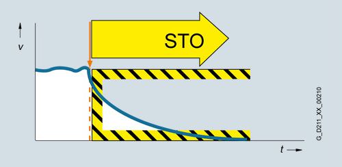
Safe Torque Off (STO)
Function description
This function prevents unexpected starting according to EN 60204-1 Section 5.4. Safe Torque Off disables the control of the power unit, preventing a potentially hazardous torque (corresponds to Stop Category 0 according to EN 60204-1). The drive is reliably torque-free. This state is monitored internally in the drive.
Under Extended Functions, STO can also be controlled via the TM54F Terminal Module or PROFIsafe.
Application, customer benefits
STO has the immediate effect that the drive cannot supply any torque-generating energy. STO can be used wherever the drive will naturally reach a standstill due to load torque or friction in a sufficiently short time or when "coasting down" of the drive will not have any relevance for safety.
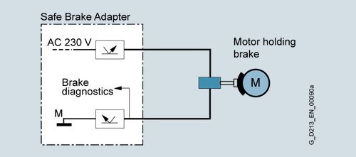
Safe Brake Control (SBC)
Function description
The Safe Brake Control SBC is used to control holding brakes, which are active in the no-current state, e.g. motor holding brakes (actuated using spring force). The brake is controlled through two channels in a safety-relevant fashion.
- Note 1: The Safe Brake Control does not detect mechanical faults in the brake, for example worn brake pads.
- Note 2: For Motor Modules, Booksize format, the terminals for the motor brake are integrated. For the chassis format, an additional Safe Brake Adapter (SBA) is required (see SINAMICS S120 Chassis Format Units, Supplementary system components).
Application, customer benefits
In conjunction with STO and SS1, SBC can also be activated. After switching off the torque-generating energy, SBC offers the possibility to safely control a holding brake at the motor; for example, to prevent hanging/suspended axes from sagging.
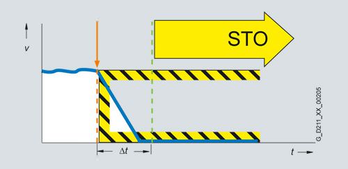
Safe Stop 1 (SS1, time-controlled, without encoder; Basic Safety Function)
Function description
The Safe Stop 1 function can safely stop the drive in accordance with EN 60204-1, Stop Category 1. When the SS1 function is selected, the drive independently brakes along a quick stop ramp (OFF3) and Safe Torque Off and Safe Brake Control (if enabled) are activated when the selected safety delay time has expired.
Application, customer benefits
When activating the stop function, if the drive does not come quickly enough to a standstill as a result of the load torque, then it can be actively braked by the converter. As a result of this integrated fast brake function, frequently it is possible to eliminate mechanical brakes which wear, or to reduce the load on them. This means that maintenance costs and stress on the machine can be reduced.
Safe Stop 1 (SS1, time and acceleration controlled, with sine-cosine encoder; Extended Safety Function)
Function description
The Safe Stop 1 function can safely stop the drive in accordance with EN 60204-1, Stop Category 1. When the SS1 function is selected, the drive independently brakes along a quick stop ramp, the deceleration is monitored (OFF3) and Safe Torque Off and Safe Brake Control (if enabled) are automatically activated when the selected safety delay time has expired.
Application, customer benefits
When activating the stop function, if the drive does not come quickly enough to a standstill as a result of the load torque, then it can be actively braked by the converter. As a result of this integrated fast brake function, frequently it is possible to eliminate mechanical brakes which wear, or to reduce the load on them. This means that maintenance costs and stress on the machine can be reduced.
Safe Stop 2 (SS2, with sine-cosine encoder)
Function description
The Safe Stop 2 function can safely stop the drive in accordance with EN 60204-1, Stop Category 2. When the SS2 function is selected, the drive brakes autonomously along a quick stop ramp (OFF3). In contrast to SS1, the drive control remains operational afterwards, i.e. the motor can supply the full torque required to maintain the actual position. Standstill is safely monitored (Safe Operating Stop function, SOS).
Application, customer benefits
Just the same as for SS1, the drive is independently braked when the stop function is selected. Contrary to SS1, also at standstill, the drive can provide the full torque.
Safe Stop 1 (SS1) and Safe Stop 2 (SS2) with Safe Acceleration Monitor (SAM, with sine-cosine encoder)
For the Extended Functions Safe Stop 1 (SS1) and Safe Stop 2 (SS2) with SAM, during braking, the acceleration is safely monitored (SAM) in order to identify faults already during the braking phase.
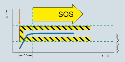
Safe Operating Stop (SOS, with sine-cosine encoder)
Function description
The Safe Operating Stop function constitutes safe standstill monitoring. The drive control remains in operation. The motor can therefore deliver the full torque to hold the current position. The actual position is reliably monitored. In contrast to safety functions SS1 and SS2, the speed setpoint is not influenced autonomously. After SOS has been selected, the higher-level control must bring the drive to a standstill within a parameterized safe time Δt and then hold the position setpoint. After the time Δt has expired, SOS is activated and monitored to ensure that the actual standstill position is not left.
Application, customer benefits
SOS is the ideal function for all those applications for which the machine or parts of the machine must be at a safe standstill for certain machining steps, but where the drive must also supply a holding torque.
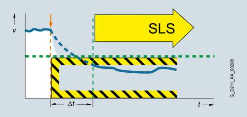
Safely-Limited Speed (SLS, with sine-cosine encoder)
Function description
Using the Safely-Limited Speed function, the drive is monitored against a parameterizable maximum velocity. Four different limit values can be activated. Just the same as for SOS, the speed setpoint is not independently influenced. After SLS has been selected, the higher-level control must bring the drive to below the selected velocity limit within a parameterizable time Δt.
Application, customer benefits
When setting-up many machines operating personnel must work on the machine as it rotates. This must either be done in steps, because the dangerous area must always be exited at each start, or alternatively, the operator works at the machine while it moves and is therefore exposed to an increased risk. When using the SLS function, a considerable amount of time can be saved – and it is still guaranteed that the operating personnel are safe. For this purpose, the drive velocity can be safely limited to a safe low level. The selectable wait time until SLS is activated allows the drive control to run-down the coordinated axes in a controlled fashion.
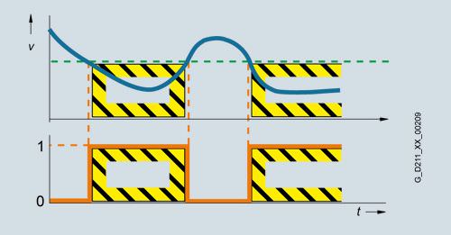
Safe Speed Monitor (SSM, with sine-cosine encoder)
Function description
The Safe Speed Monitor function supplies a safety feedback signal (high active) if the drive falls below a selectable velocity limit value. Contrary to the functions described above, there is no drive-based fault response when the limit value is exceeded.
Application, customer benefits
The safety SSM feedback signal can be used in a higher-level control for safety-relevant responses. The higher-level safety control can flexibly respond to the signal, depending on the particular situation, as there is no drive-based response when the limit value is exceeded. For example, using the SSM signal, a protective door can be released after a non-hazardous velocity is reached.
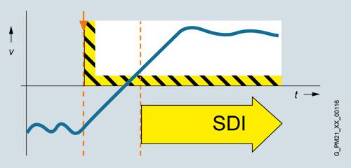
Safe Direction (SDI, with sine-cosine encoder)
Function description
The SDI function ensures that the drive can only rotate in the selected direction.
Deviation from the direction of rotation currently being monitored is detected reliably and the configured drive-integrated fault reaction is initiated. It is possible to select which direction of rotation is to be monitored.
Application, customer benefits
The SDI function is used when the drive may only move in one direction. A typical application is to permit the operator access to a danger zone, as long as the machine is rotating in the safe direction, i.e. away from the operator. In this state, the operator can feed material into the work zone/remove material from the work zone without danger.
The function saves the use of external components e.g. speed monitors and the associated wiring. The release of a danger zone, while the machine is moving away from the operator, increases productivity. Without the SDI function, the machine must be safely stopped during material loading and removal.
PROFIsafe
PROFIsafe is an open communication standard, that facilitates standard and safety-relevant communication along one communication path (hard-wired or wireless). As a consequence, a second, separate bus system is not required. The telegrams that are sent are continually monitored to ensure safety-relevant communication. Possible errors such as telegrams that have been lost, repeated or received in the incorrect sequence etc. are avoided. This is done by consecutively numbering the telegrams in a safety-relevant fashion, monitoring their reception within a defined time and transferring an ID for transmitter and receiver of a telegram. Further, a cyclic redundancy check CRC (cyclic redundancy check) is performed.
SINAMICS 120 supports the PROFIsafe profile, based on PROFIBUS as well as on PROFINET.
Licensing
The Safety Integrated Basic Functions do not require a license. A license is, however, required for each axis with safety functions in the case of Safety Integrated Extended Functions. It is irrelevant which safety functions are used and how many.
Licenses required for the SINAMICS S120 chassis format can be ordered, depending on the axes, as Z option F01 to F05 for the CompactFlash card. For SINAMICS S120 Cabinet Modules, depending on the axes, they can be ordered with safety options K01 to K05 for Motor Modules.
Refer to the section, Supplementary system components for the order numbers of the CompactFlash cards.
Note: Presently, a maximum of 5 safety axes with Extended Functions are possible on a CU320-2. CU310/D410 Control Units are intended for the control of a single axis only. This means that only one license is required for the Extended Safety functions for these Control Units (option F01).
An overview of the SINAMICS Safety Integrated functions plus their boundary conditions is shown in the following table:
Function | Control | Underlying function | Reaction to limit overshoot | Encoder required | License required |
|---|---|---|---|---|---|
Safety Basic Functions | |||||
STO |
| SBC (if activated) | – | No | No |
SS1 |
| STO, after a parameterized delay time has expired | STO | No | No |
SBC |
| – | – | No | No |
Safety Extended Functions | |||||
STO |
| SBC (if activated) | – | Yes 4) | Yes (each safety axis) |
SS1 |
| STO is activated after the shutdown conditions have been fulfilled | STO | Yes 4) | Yes (each safety axis) |
SBC |
| – | – | Yes 4) | Yes (each safety axis) |
SS2 |
| STO is activated after the shutdown conditions have been fulfilled | STO | Yes 4) | Yes (each safety axis) |
SLS |
| Up to four maximum speeds for operation can be parameterized | STO, SS1 or SOS (can be parameterized) | Yes 4) | Yes (each safety axis) |
SOS |
| For closed-loop speed control: The position is monitored from standstill | STO or SS1 (can be parameterized) | Yes 4) | Yes (each safety axis) |
SSM |
| Safe limit value monitoring in both directions of rotation, no independent drive response. A safety-relevant signal for further operation is generated. | – | Yes 4) | Yes (each safety axis) |
SDI |
| – | STO, SS1 or SOS (can be parameterized) | Yes 4) | Yes (each safety axis) |
1) In addition for SINAMICS S120 Cabinet Modules and SINAMICS S150 Converter Cabinet Units.
2) Safe Brake Adapter has been released from firmware version 4.4.
3) For SINAMICS S120 Cabinet Modules and SINAMICS S150 Converter Cabinet Units as option K87.
4) The Safety Integrated Extended Functions require a sine-cosine encoder to sense the motor speed. Possible encoder evaluation units SMC20, SMI20, SME20/25/120/125.
The principle of operation of Safety Integrated
Two independent shutdown paths
There are two shutdown paths that are independent of one another.
All shutdown paths are low active. This therefore ensures that when a component fails or there is a wire break, then the system always goes into the safe state. When a fault is detected in the shutdown paths, the Safe Torque Off or Safe Stop 1 function (depending on the parameterization, also refer to the table above) is activated and a restart is prevented.
Two-channel monitoring structure
All of the hardware and software functions important for Safety Integrated are implemented in two independent monitoring channels (e.g. shutdown paths, data management, data comparison). The safety-relevant data in the two monitoring channels is cyclically compared crosswise.
The monitoring functions in each monitoring channel are based on the principle that before a particular action, there must be a defined state, and after the action there must be a specific feedback. If this expectation is not fulfilled in a monitoring channel, then the drive is shutdown through two channels and the appropriate signal output.
Forced checking procedure using a test stop
In order to fulfill the requirements of EN ISO 13849-1 (previously EN 954-1) and IEC 61508 regarding early fault detection, the functions and the shutdown paths must be tested within a specific time period at least once to ensure that they are operating correctly. This must be realized either cyclically and manually or the test stop must be automatically initiated as part of the process. The test stop cycle is monitored, and after a specific time has been exceeded, an alarm is output.
A test top does not require a power on. The acknowledgment is realized when deselecting the test stop request.
When the machine is operational, it can be assumed that there is no risk for personnel as a result of the appropriate safety equipment (e.g. protective doors). As a consequence, the user is only made aware of the forced checking procedure that is required using an alarm, and is requested to perform the forced checking procedure at the next possible opportunity.
Examples for performing the forced checking procedure:
- When the drives are stationary after switching-on the system
- Before opening the protective door
- In a specified rhythm (e.g. every 8 hours)
- In the automatic mode, time and event-triggered
Технические данные
The most important directives and standards are listed below. These are used as basis for the SINAMICS S120 Chassis Format Units drive system and they must be carefully observed to achieve an EMC-compliant configuration that is safe both functionally and in operation.
European directives | |
|---|---|
2006/95/EG | Low-voltage directive: |
2004/108/EC | EMC directive: |
European standards | |
EN 954-1 1) | Safety of machinery – safety-related parts of control systems; |
EN ISO 13849-1 | Safety of machinery – safety-related parts of control systems; |
EN 60146-1-1 | Semiconductor converters – General requirements and line-commutated converters |
EN 60204-1 | Safety of machinery – Electrical equipment of machines; |
EN 60529 | Degrees of protection provided by enclosures (IP code) |
EN 61508-1 | Functional safety of electrical/electronic/programmable electronic safety-related systems |
EN 61800-2 | Variable-speed electric drives |
EN 61800-3 | Variable-speed electric drives |
EN 61800-5-1 | Adjustable-speed electrical power drive systems |
EN 61800-5-2 | Adjustable speed electrical power drive systems |
North American standards | |
UL 508A | Industrial Control Panels |
UL 508C | Power Conversion Equipment |
CSA C22.2 No. 14 | Industrial Control Equipment |
Approvals | |
cULus, cURus | Testing by UL (Underwriters Laboratories, www.ul.com) according to UL and CSA standards |
1) Will be replaced by EN ISO 13849-1 at the end of 2011.
Test symbols:
(→ Appendix, Approvals)


 Ответ от производителя может занять до 5 дней и более.

