Active Field Distributors Siemens
Обзор
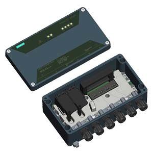
Active Field Distributor AFD4
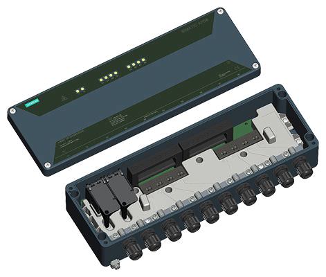
Active Field Distributor AFD8
Active Field Distributor AFD
Active field distributors (AFD) can be operated in environments in accordance with Division 2, Zone 2 or Zone 22. It is offered with the following models:
- AFD4 or AFD4 FM with 4 spur line connections for 1 field device each
- AFD8 with 8 spur line connections for 1 field device each
An AFD4/AFD4 FM can therefore connect up to 4 field devices, and an AFD8 can connect up to 8 standard-conform field devices, via short-circuit proof spur line connections to a fieldbus segment (line/ring) with automatic bus termination. This applies to both PA field devices (PROFIBUS PA) as well as FF field devices (FOUNDATION Fieldbus H1).
The fieldbus segment can be connected to a single or redundant PROFIBUS DP via a PA or FF router and can thus be seamlessly integrated into the SIMATIC PCS 7 process control system.
Up to 8 active field distributors AFD with a total of up to 31 connected field devices can be operated for each fieldbus segment. The number of field devices is also limited by the current consumption of the field devices. A maximum of 60 mA per spur line and a maximum of 1 A per segment is available for the field devices.
An AFD in a ring segment can be replaced during operation without failure of the segment.
For compliance with IP66 protection, it is necessary to protect unused spur line connections using plugs.
Differences between AFD4 and AFD4 FM
The AFD4 FM with cFMus approval is adapted to the special requirements for product models of the AFD4 active field distributor in the USA and Canada . The AFD4 FM features threaded plugs ex factory, because the cable glands of the AFD4 do not conform to the requirements of cFMus.
The threaded plugs for connecting the main and spur lines must be replaced by the cable glands and cables listed by UL or CSA. This must conform to the US National Electrical Code (NEC) and Canadian Electrical Code (CEC). The user is responsible for the selection and ordering.
Available suppliers for suitable cable glands:
- Cooper Capri SAS
- CMP products
Due to the larger bushing for the main line (M20 instead of M16), sheathed main line cables can also be used for AFD4 FM.
The relevant requirements of the US National Electrical Code (ANSI/NFPA‑70 NEC) must be met for the installation of the AFD4 FM.
Active field distributor AFDiS
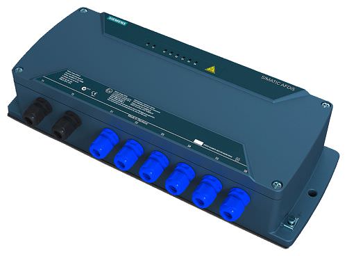
Active field distributor AFDiS
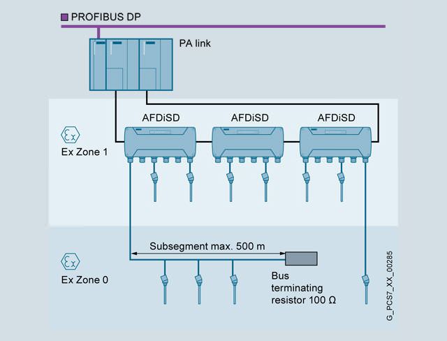
The active field distributor AFDiS (Active Field Distributor intrinsically Safe) can be operated in environments in accordance with Ex zone 1/21 and 2/22. It can integrate up to 6 intrinsically-safe PA or FF field devices into a fieldbus segment (line/ring) via its intrinsically-safe, short-circuit-proof spur line connections. Instead of the spur line, it is also possible to use a subsegment for 3 to 4 devices with a max. length of 500 m at connection S1 of the AFDiS. The spur lines with Ex [ia] type of protection as well as the subsegment can be routed into Zone 0/20.
Up to 5 field distributors AFDiS with a total of up to 31 field devices can be operated in a fieldbus segment. The limitation to 5 field distributors is also mandatory for mixed operation of AFD and AFDiS.
The number of field devices per segment additionally depends on the current consumption of the devices. A current of 1 A is available for all field devices of the segment.
With the integrated repeater function, the AFDiS has the following advantages compared to the AFD:
- Spur line lengths are independent of the total number of spur lines in the bus segment
- Spur line lengths need not be be taken into account when determining the total length of the bus segment
Under the following conditions, an AFDiS in a ring segment can be replaced during operation without failure of the segment: Installation in Zone 2/22 or in a non-hazardous area.
For compliance with IP66 protection, it is necessary to protect unused spur line connections using plugs.
Active Field Splitter AFS
The active field splitter (AFS) connects a PA or FF line segment with a redundant coupler pair of a PA or FF router. The AFS interconnects the line segment with the respective active coupler.
The PA or FF line segment can be connected to the AFS via one or two (center feed) equivalent Y-connectors out of a total of 4. For the center feed, the line segment is connected via the two Y-connectors (bus termination switch on both FDC 157 couplers set to "OFF").
For compliance with IP66 protection, it is necessary to protect unused connections using plugs.
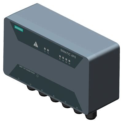
AFS: Active Field Distributor for FOUNDATION Fieldbus H1
Технические данные
Active Field Distributor AFD | |
|---|---|
General data | |
Connection of field devices |
|
Degree of protection | IP66 |
Voltages, currents, potentials | |
Power supply | Via bus, no auxiliary power necessary |
Rated supply voltage, permissible range | 16 to 32 V DC |
Reverse polarity protection (together with FDC 157) | Yes |
Overvoltage protection | No |
Current consumption | |
| |
| 24 mA |
| 34 mA |
| |
| 24 mA + total current of all field devices |
| 34 mA + total current of all field devices |
| 30 mA |
| |
| 264 mA |
| 514 mA |
Power loss | |
| Min. 384 mW; max. 3.2 W |
| Min. 544 mW; max. 4.1 W |
Grounding | Direct, via grounding rail |
Electrical isolation between main line and spur lines | No |
Connections, interfaces | |
Main line | |
Number of connections | 2 |
Cable bushings | |
| Cable glands M16 |
| Terminal screws M20 |
| Cable glands M16 |
Interfaces | PROFIBUS PA and FOUNDATION Fieldbus H1 |
Automatic bus terminator | Yes |
Spur lines | |
Number of connections | |
| 4 |
| 8 |
Cable bushings | |
| Cable glands M16 |
| Terminal screws M16 |
| Cable glands M16 |
Short-circuit-proof | Yes |
Intrinsically-safe acc. to FISCO | No |
Current Imax (DC) on spur lines 1 to 4 (AFD4) or 1 to 8 (AFD8) | 60 mA |
Short-circuit current (test current) | 6 mA |
Debounce logic | Yes |
No-load voltage | < 30 V |
Current output to field devices | |
| Max. 240 mA |
| Max. 480 mA |
Status, interrupts, diagnostics | |
Status indicator | Yes |
Diagnostics function | Yes |
Diagnostics LED | Yes |
Interrupts | No |
Climatic conditions | |
Permissible operating temperature | -40 to +70 °C |
Permissible storage/transport temperature | -40 to +85 °C |
Relative humidity during operation | Max. 95% |
Approvals for potentially explosive atmospheres | |
| Zone 2 |
| Zone 22 |
Dimensions and weight | |
Dimensions (W × H × D) in mm (without screwed glands) | |
| 220 × 120 × 83 |
| 360 × 120 × 83 |
Weight | |
| 2 000 g |
| 3 000 g |
Approvals, standards | |
AFD4 and AFD8 | |
| According to 94/9/EG (formerly ATEX 100a), 2004/108/EG and 2006/95/EG |
| II 3G Ex nA ic [ic] IIC T4 Gc |
| IECEx DEK 12.0069X |
| Korea Certification |
| Ex nA [ic] IIC T4 Gc |
AFD4 FM | |
| FM Class 3600, 3611, 3810, ANSI/ISA 60079-0/-31, ANSI/ISA 60529, ANSI/NEMA250 |
Active Field Distributors AFDiS | |
|---|---|
General data | |
Connection of field devices |
|
Degree of protection | IP66 |
Voltages, currents, potentials | |
Power supply | Via bus, no auxiliary power necessary |
Rated supply voltage, permissible range | 16 to 32 V DC |
Reverse polarity protection (together with FDC 157) | Yes; up to 1 A |
Overvoltage protection | No |
Current consumption | |
| ≤ 64 mA + (0.838 × aggregate current of all field devices) |
| ≤ 67 mA + (1.008 × aggregate current of all field devices) |
| ≤ 74 mA + (1.246 × aggregate current of all field devices) |
Power loss | Min. 1.4 W; max. 5.9 W |
Grounding | Direct, via connecting bar |
Electrical isolation between main line and spur lines | Yes |
Test voltage | 2550 V DC, 2 s |
Connections, interfaces | |
Main line | |
Number of connections | 2 |
Cable bushings | Cable glands M16 |
Interfaces | PROFIBUS PA and FOUNDATION Fieldbus H1 |
Automatic bus terminator | Yes |
Spur lines | |
Number of connections | 6 |
Cable bushings | Cable glands M16 |
Short-circuit proof | Yes |
Intrinsically-safe acc. to FISCO | Yes |
Current Imax | |
| 60 mA |
| 40 mA |
| 180 mA |
Short-circuit current (test current) | 5 mA |
Debounce logic | Yes |
No-load voltage | Max. 15.3 V |
Current output to field devices | Max. 260 mA |
Status, interrupts, diagnostics | |
Status indicator | Yes |
Diagnostics function | Yes |
Diagnostics LED | Yes |
Interrupts | No |
Climatic conditions | |
Permissible operating temperature | -40 to +70 °C |
Permissible storage/transport temperature | -40 to +85 °C |
Relative humidity during operation | Max. 95 % |
Approvals for potentially explosive atmospheres | |
| Zone 1 and Zone 2 |
| Zone 21 and Zone 22 |
Dimensions and weight | |
Dimensions (W × H × D) in mm | 380 × 85 × 170 |
Weight | 4 500 g |
Approvals, standards | |
| According to 94/9/EG (formerly ATEX 100a), 2004/108/EG and 2006/95/EG |
| Ex e ib mb [ia IIC Ga] [ia IIIC Da] IIC T4 Gb |
| IECEx KEM 10.0026 |
| Korea Certification |
| Ex e ib mb [ia IIC Ga] [ia IIIC Da] IIC T4 Gb |
| Ex e ib mb [ia IIC GA] [iaD] IIC T4 Gb; |
Active Field Distributors AFS | |
|---|---|
General data | |
Connection of field devices |
|
Degree of protection | IP66 |
Voltages, currents, potentials | |
Power supply | Via bus, no auxiliary power necessary |
Rated supply voltage, permissible range | 16 to 32 V DC |
Reverse polarity protection (together with FDC 157) | Yes |
Overvoltage protection | No |
Current consumption at idle | 54 mA |
Power loss | Min. 864 mW; max. 2.13 W |
Output current for supplying all field devices of the fieldbus segment (for dimensioning the device configuration) | 1 A |
Grounding | Direct, via connecting bar |
Connections, interfaces | |
Main lines to the FDC 157 couplers | |
Number of connections | 2 |
Cable bushings | Cable glands M16 |
Automatic bus terminator | No |
Maximum permissible continuous main line current | 1 A |
Y-connections for fieldbus line segment | |
Number of connections | 1 or 2 (with center feed) |
Cable bushings | Cable glands M16 |
Interfaces | PROFIBUS PA and FOUNDATION Fieldbus H1 |
Short-circuit proof (together with FDC 157) | Yes |
Intrinsically-safe acc. to FISCO | No |
Current Imax on Y (limited by FDC 157) | 1 A |
Debounce logic | No |
Continuous output voltage | Max. 32 V |
Current output to field devices | Max. 1 A |
Status, interrupts, diagnostics | |
Status indicator | Yes |
Diagnostics function | Yes |
Diagnostics LED | Yes |
Interrupts | No |
Climatic conditions | |
Permissible operating temperature | -40 to +70 °C |
Permissible storage/transport temperature | -40 to +85 °C |
Relative humidity during operation | Max. 95 % |
Approvals for potentially explosive atmospheres | |
| Zone 2 |
| Zone 22 |
Dimensions and weight | |
Dimensions (W × H × D) in mm (without screwed glands) | 220 × 120 × 83 |
Weight | 2 000 g |
Approvals, standards | |
| According to 94/9/EG (formerly ATEX 100a), 2004/108/EG and 2006/95/EG |
| II 3G Ex nA IIC T4 Gc |
| IECEx DEK 12.0069X |
| Korea Certification |


 Ответ от производителя может занять до 5 дней и более.

