LOHER DYNAVERT I Current-source Inverters Siemens
Область применения
Typical applications
- Power stations and utilities
- Plastic industry
- Basic materials industry
- Test stands
- Conveyor technology and applications in general machinery construction
- Retrofit for SIMOVERT A drives
Обзор
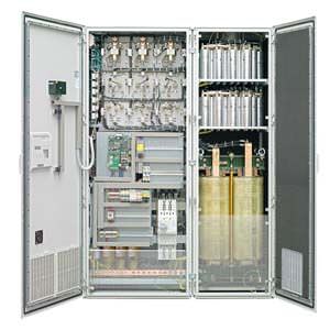
LOHER DYNAVERT I Current‑Source Inverters
General description
LOHER DYNAVERT I drive units are currentsource DC link inverters that are used to control induction motors. They have a fully controlled B6 bridge circuit on the line side and a B6 inverter circuit on the output side, which utilizes the principle of interphase commutation; this distributes the DC link current from the DC link reactors with a square waveform with frequency f to the motor winding. As a consequence, the motor cable length is almost unlimited.
The power flows from the line supply to the motor for a motoring load. For regenerative operation, the rectifier on the line-side feeds the regenerated energy back into the line supply. This means that from the inherent principle, 4‑quadrant operation is possible without requiring any additional measures. 12- and 24‑pulse versions further reduce the harmonics fed back into the line supply. For this reason LOHER DYNAVERT I is the ideal replacement for SIMOVERT A.
Features
Explosion protection
- ATEX‑certified for motors located in hazardous zones with Accessory kit S, also with very long motor cable length
Emergency Off
- The Emergency Off function prevents unexpected starting in compliance with EN 60204‑1, implemented according to EN 954‑1, Category 3, respectively SIL2 with Accessory kit S
Power unit
- 12- and 24‑pulse input optional posible. For this reason gi line supply (basic fundamental) of 99.9 % is possible
- This corresponds to the EMC Directives (EN 61800‑3 environment 2) as a result of the line filter integrated as standard
- Low harmonics fed back into the line supply as a result of the integrated line reactor
- Long motor cable lengths possible inherent to the system
- Insulation monitoring for IT line supplies for 500 V/690 V drive units as well as ground fault monitoring for TN and TT line supplies integrated in the 400 V drive units
- Wide supply voltage range
- Normal fuses can be used for protection (gL characteristic)
Control section
- High level of personnel and plant protection through protective separation between the analog and digital control peripheral and the power unit according to VDE 0106/EN 50178
Operator control and setting
- Transparent operator control and setting using a menu-prompted 4‑line plain text display with membrane keypad at the drive inverter – or up to 1000 m away in the main control room via RS485
- Extensive functions using the Windowsbased PC operator control program
Communication
- Communication via a conventional terminal strip with freely‑programmable digital and analog inputs/outputs, with
- parameterizable limit value signals
- parameterizable timers
- parameterizable damping elements
- parameterizable drive inverter behavior when inputs/outputs respond
- Communication and parameterization via
- PC using IMS (Inverter Management Software) via RS232/RS485
- external operator panel via RS485
- bus systems such as Profibus DP or Modbus RTU
Drive behavior for LOHER DYNAVERT I
- Two closed‑loop control types for induction motors:
- Speed control
- Torque control
- Full 4‑quadrant operation with regenerative braking as standard
The following generally apply
- Automatic slip compensation
- Stall protection using current limiting control
- Flying restart circuit to connect to a rotating motor
Особенности
Customer benefits
- Cabinet units in IP21 or higher degrees of protection
- All of the drive units have their own connection space
- Compact dimensions
- Equipped with radio interference suppression
- Low harmonics fed back into the line supply, mainly on 12- and 24‑pulse versions
- Almost unlimited motor cable lengths possible inherent to the system
- High overvoltage strength, e.g. load shedding of turboset in power stations
- Wide supply voltage range
- Full 4‑quadrant operation as standard
- Same user interface/software as LOHER DYNAVERT T
Технические данные
Rated input voltage | Typ. motor rated power for cabinet systems |
|---|---|
400 V | 15 ... 630 kW |
500 V | 15 ... 800 kW |
690 V | 45 ... 5600 kW |
950 V | 630 ... 6000 kW |
Brief overview | |
|---|---|
Line supply voltage | 3 ~ AC 400 ... 1140 V |
Line supply cos phi (1) | Depends on the motor |
Line supply frequency | 50 Hz, optional 60 Hz |
Maximum output frequency | 60 Hz, higher on request |
Output voltage | 3 × 0 ... line supply voltage |
Motor cable length | 500 m, longer on request |
Degree of protection | IP21, higher degrees of protection optionally available |
Features
Explosion protection
- ATEX-certified for motors located in hazardous zones with Accessory kit S, also with very long motor cable length
Emergency Off
- The Emergency Off function prevents unexpected starting in compliance with EN 60204‑1, implemented according to EN 954‑1, Category 3, respectively SIL2 with Accessory kit S
Power unit
- 12- and 24-pulse input optional possible. For this reason gi line supply(basic fundamental) of 99.9 % is possible
- This corresponds to the EMC Directives (EN 61800‑3 environment 2) as a result of the line filter integrated as standard
- Low harmonics as a result of the integrated line reactor
- Long motor cable lengths possible inherent to the system
- Insulation monitoring for IT line supplies for 500/690 V drive units as well as ground fault monitoring for TN and TT line supplies integrated in the 400 V drive units
- Wide supply voltage range
- Normal fuses can be used for protection (gL characteristic)
Control section
- High level of personnel and plant protection through protective separation between the analog and digital control peripheral and the power unit according to VDE 0106 / EN 50178
Operator control and setting
- Transparent operator control and setting using a menu-prompted 4-line plain text display with membrane keypad at the drive inverter
- or up to 1000 m away in the main control room via RS485
- Extensive functions using the Windows-based PC operator control program
Communication
- Communication via conventional terminal strip with freely-programmable digital and analog inputs / outputs, with
- parameterizable limit value signals
- parameterizable timers
- parameterizable damping elements
- parameterizable drive inverter behavior when inputs/outputs respond
- Communication and parameterization via
- PC using IMS (Inverter Management Software) via RS232/RS485
- external operator panel via RS485
- bus systems such as Profibus DP or Modbus RTU
Drive behavior for LOHER DYNAVERT I
- Two closed-loop control types for induction motors:
- Speed control
- Torque control
- Full 4-quadrant operation with regenerative braking as standard
The following generally apply
- Automatic slip compensation
- Stall protection using current limiting control
- Flying restart circuit to connect to a rotating motor


 Ответ от производителя может занять до 5 дней и более.

