Racks Siemens
Область применения
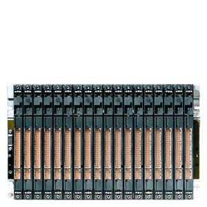
The subracks form the basic mechanical framework of the SIMATIC S7-400. Their functions are as follows:
- Mechanical fixing of the modules
- Supplying the modules with the operating voltages
- Connecting the individual modules over the backplane bus
The subracks are designed for wall mounting and installation in frames and cabinets
Various subracks are available for setting up the SIMATIC S7-400.
UR1 (Universal Rack)
- For setting up central controllers and expansion units
- For holding up to 18 modules
- Also suitable for S7-400H
- Also available as aluminum rack
UR2 (Universal Rack)
- For setting up central controllers and expansion units
- For holding up to 9 modules
- Also suitable for S7-400H
- Also available as aluminum rack
CR2 (Central Rack)
- For setting up central controllers
- For holding up to 18 modules
- Segmented rack:
For operating two mutually independent S7-400 CPUs without S7-400 Multicomputing, but with communication between the CPUs over the backplane bus (C bus). Both CPUs can address their own local I/O modules (segmented P bus).
CR3 (Central Rack)
- For configuring central racks
- Optimized for distributed automation solutions due to holding up to 4 modules
UR2-H
- For configuring a complete S7-400H system in one subrack
- Also suitable for S7-400:
Operation of 2 separate CPUs with their own I/O (separate P and C buses) - Can also be used as an expansion unit
- For holding up to 18 modules
- Also available as aluminum rack
ER1 (Extension Rack)
- For setting up expansion units economically
- For holding up to 18 modules with restricted functionality
- Also suitable for S7-400H
- Also available as aluminum rack
ER2 (Extension Rack)
- For setting up expansion units economically
- For holding up to 9 modules with restricted functionality
- Also suitable for S7-400H
- Also available as aluminum rack
Обзор
- The basic mechanical framework of the SIMATIC S7-400/S7-400H
- For accommodating the modules, supplying them with operating voltage and connecting them via the backplane bus
- Several versions for configuring central controllers and expansion racks
Дизайн
All racks included:
- Mounting rail with threaded bolts for fixing the modules and lateral cutouts for mounting the rack
- Plastic parts serve as guides when swinging the modules into place
- Connection for protective conductors
- Backplane bus with plug-in connections
UR1 for central controllers
- 18 single-width slots
- Always required: Power module (PS) and one CPU
- Can be expanded centrally (up to 5 m) and in distributed configuration (up to 600 m)
- The following are required when expanded:
- Interface modules (send IMs); max. 6 interface modules can be plugged in
- Up to 21 expansion units can be connected
UR2 for central controllers
- 9 single-width slots
- Always required: Power module (PS) and one CPU
- Can be expanded centrally (up to 5 m) and in distributed configuration (up to 600 m)
- The following are required when expanded:
- Interface modules (send IMs); max. 6 interface modules can be plugged in
- Up to 21 expansion units can be connected
CR2 for central controllers
- 18 single-width slots; 2 segments with 8 or 10 slots
- Always required: Power module (PS) und 2 CPUs
- Can be expanded centrally (up to 5 m) and in distributed configuration (up to 600 m)
- The following are required when expanded:
- Interface modules (send IMs). Max. 6 interface modules can be plugged in
- Up to 21 expansion units can be connected.
- 2 CPUs can be operated next to each other, each with its own I/O:
2 P bus segments with 10 or 8 slots for 1 CPU each with its own I/O - C bus throughout: C bus nodes can be addressed from both segments.
CR3 for central controllers
- 4 single-width slots
- Always required: Power module (PS) and one CPU
- Can be expanded centrally (up to 5 m) and in distributed configuration (up to 600 m)
- The following are required when expanded:
- Interface modules (send IMs); max. 2 interface modules can be plugged in
- Up to 16 expansion units can be connected
- C bus and P bus throughout
UR2-H
- 18 single-width slots; 2 segments with 9 slots each
- Always required: 2 power modules (PS) und 2 CPUs
- Can be expanded centrally (up to 5 m) and in distributed configuration (up to 600 m)
- The following are required when expanded:
- Interface modules (send IMs); max. 6 interface modules can be plugged in
- Up to 21 expansion units can be connected
- 2 CPUs can be operated next to each other, each with its own I/O:
2 P bus segments and 2 C bus segments with 9 slots each for 1 CPU each with its own I/O - C bus throughout: C bus nodes can be addressed from both segments
UR1 for expansion units
- 18 single-width slots
- Always required: Interface module (receive IM)
UR2 for expansion units
- 9 single-width slots
- Always required: Interface module (receive IM)
ER1 for expansion units
- 18 single-width slots
- Always required: Interface module (receive IM)
- P bus with restricted functionality:
- No alarm processing
- No battery backup of the plugged-in modules
- No 24 V DC supply of the modules
- No C bus
- The following can be used:
- SM modules
- Receive IM
- Power supply module
ER2 for expansion units
- 9 single-width slots
- Always required: Interface module (receive IM)
- P bus with restricted functionality:
- No alarm processing
- No battery backup of the plugged-in modules
- No 24 V DC supply of the modules
- No C bus
- The following can be used:
- SM modules
- Receive IM
- Power supply module
Технические данные
Order number | 6ES7400-1TA01-0AA0 | 6ES7400-1TA11-0AA0 | 6ES7400-1JA01-0AA0 | 6ES7400-1JA11-0AA0 | 6ES7401-2TA01-0AA0 | 6ES7401-1DA01-0AA0 | |
|---|---|---|---|---|---|---|---|
S7-400, UR1 RACK, 18 SLOTS | S7-400, UR1 RACK ALU, 18 SLOTS | S7-400, UR2 RACK, 9 SLOTS | S7-400 MOD.TR ALU UR2, 9 SLOTS | SIMATIC S7-400, CR2 RACK, | S7-400 MOD. , CR3 RACK,4 SLOTS | ||
Hardware configuration |
|
|
|
|
|
| |
Rack |
|
|
|
|
|
| |
| Yes | Yes | Yes | Yes | Yes | Yes | |
| Yes | Yes | Yes | Yes | Yes | Yes | |
Slots |
|
|
|
|
|
| |
| 18 | 18 | 9 | 9 | 18; 2 segments with 8 or 10 slots | 4 | |
Dimensions |
|
|
|
|
|
| |
Width | 482.5 mm | 482.5 mm | 257.5 mm | 257.5 mm | 482.5 mm | 130 mm | |
Height | 290 mm | 290 mm | 290 mm | 290 mm | 290 mm | 290 mm | |
Depth | 27.5 mm | 27.5 mm | 27.5 mm | 27.5 mm | 27.5 mm | 27.5 mm | |
Weights |
|
|
|
|
|
| |
Weight, approx. | 4 200 g | 3 000 g | 2 200 g | 1 500 g | 4 200 g | 750 g | |
Order number | 6ES7400-2JA00-0AA0 | 6ES7400-2JA10-0AA0 | 6ES7403-1TA01-0AA0 | 6ES7403-1TA11-0AA0 | 6ES7403-1JA01-0AA0 | 6ES7403-1JA11-0AA0 | |
|---|---|---|---|---|---|---|---|
SIMATIC S7-400H, UR2-H RACK, 18 SLOTS | S7-400 MOD.TR ALU UR2-H, 18 SLOTS | SIMATIC S7-400, ER1 EXP. RACK, | S7-400, ER1 EXPANSION RACK ALU, 18 SLOTS | SIMATIC S7-400, ER2 EXP. RACK, | S7-400, ER2 EXPANSION RACK ALU, 9 SLOTS | ||
Hardware configuration |
|
|
|
|
|
| |
Rack |
|
|
|
|
|
| |
| Yes | Yes | |||||
| Yes | Yes | Yes | Yes | Yes | Yes | |
Slots |
|
|
|
|
|
| |
| 18 | 18 | 18 | 18 | 9 | 9 | |
Dimensions |
|
|
|
|
|
| |
Width | 482.5 mm | 482.5 mm | 482.5 mm | 482.5 mm | 257.5 mm | 257.5 mm | |
Height | 290 mm | 290 mm | 290 mm | 290 mm | 290 mm | 290 mm | |
Depth | 27.5 mm | 27.5 mm | 27.5 mm | 27.5 mm | 27.5 mm | 27.5 mm | |
Weights |
|
|
|
|
|
| |
Weight, approx. | 4 200 g | 3 000 g | 4 200 g | 2 500 g | 2 200 g | 1 250 g | |
Дальнейшая информация
Brochures
Information material for downloading can be found in the Internet:


 Ответ от производителя может занять до 5 дней и более.

