Characteristic curves Siemens
Обзор
Derating data
SINAMICS G180 converters and the associated system components are rated for an ambient temperature of 40 °C and installation altitudes up to 1000 m above sea level.
At ambient temperatures of > 40 °C, the output current must be reduced. SINAMICS G180 converters may not operate in ambient temperatures in excess of 50 °C except for compact units (up to 55 °C; option V63).
At installation altitudes > 1000 m above sea level, it must be taken into account that the air pressure, and therefore air density, decreases as the height increases. As a consequence, the cooling efficiency and the insulation capacity of the air also decrease.
Due to the reduced cooling efficiency, it is necessary, on the one hand, to reduce the ambient temperature, and on the other hand, to lower heat loss in the compact unit by reducing the output current, whereby ambient temperatures lower than 40 °C may be offset to compensate.
The following table specifies the permissible output currents as a function of the installation altitude and ambient temperature (the permissible compensation between installation altitude and ambient temperatures of < 40 °C (air intake temperature at the entry to the compact unit) is taken into account in the specified values).
The values apply under the precondition that a cooling air flow through the units is ensured as stated in the technical data.
Derating for air-cooled converters
Installation altitude above sea level | Current derating factor (as a % of the rated current) at an ambient/air intake temperature of 40 °C | |||||||
|---|---|---|---|---|---|---|---|---|
m | 20 °C | 25 °C | 30 °C | 35 °C | 40 °C | 45 °C | 50 °C | 55 °C1) |
0 ... 1000 | 100 % | 100 % | 100 % | 100 % | 100 % | 87.5 % | 75 % | 62.5 % |
1001 ... 1500 | 100 % | 100 % | 100 % | 100 % | 94.4 % | 82.6 % | 70.8 % | 59.0 % |
1501 ... 2000 | 100 % | 100 % | 99.4 % | 94.3 % | 88.9 % | 77.8 % | 66.7 % | 55.6 % |
2001 ... 25002) | 100 % | 97.7 % | 93.2 % | 88.4 % | 83.3 % | 72.9 % | 62.5 % | 52.1 % |
2501 ... 30002) | 95.3 % | 91.2 % | 87.0 % | 82.5 % | 77.8 % | 68.1 % | 58.3 % | 48.6 % |
3001 ... 35002)3) | 89.8 % | 86.0 % | 82.0 % | 77.8 % | 73.3 % | 64.2 % | 55.0 % | 45.8 % |
3501 ... 40002)3) | 84.4 % | 80.8 % | 77.0 % | 73.1 % | 68.9 % | 60.3 % | 51.7 % | 43.1 % |
4001 ... 45002)3) | 78.9 % | 75.6 % | 72.1 % | 68.4 % | 64.4 % | 56.4 % | 48.3 % | 40.3 % |
4501 ... 50002)3) | 73.5 % | 70.4 % | 67.1 % | 63.6 % | 60.0 % | 52.5 % | 45.0 % | 37.5 % |
1) Applies only to compact units which are not cabinet-mounted
2) Voltage derating (see voltage derating factor) is also required for compact units at an installation altitude of > 2000 m.
3) Voltage derating (see voltage derating factor) is also required for cabinet units at an installation altitude of > 3000 m.
Derating for liquid-cooled converters with coolant inlet temperature of max. 28 °C
Installation altitude above sea level | Current derating factor (as a % of the rated current) for a coolant inlet temperature of 28 °C | ||||
|---|---|---|---|---|---|
m | 18 °C | 23 °C | 28 °C | 33 °C | 38 °C |
0 ... 1000 | 100 % | 100 % | 100 % | 84.0 % | 64.2 % |
1001 ... 1500 | 100 % | 100 % | 94.4 % | 79.3 % | 60.6 % |
1501 ... 2000 | 100 % | 100 % | 88.9 % | 74.7 % | 57.0 % |
2001 ... 2500 | 100 % | 94.8 % | 83.3 % | 70.0 % | 53.5 % |
2501 ... 3000 | 98.0 % | 88.5 % | 77.8 % | 65.3 % | 49.9 % |
3001 ... 35001) | 92.4 % | 83.4 % | 73.3 % | 61.6 % | 47.1 % |
3501 ... 40001) | 86.8 % | 78.4 % | 68.9 % | 57.9 % | 44.2 % |
4001 ... 45001) | 81.2 % | 73.3 % | 64.4 % | 54.1 % | 41.4 % |
4501 ... 50001) | 75.6 % | 68.3 % | 60.0 % | 50.4 % | 38.5 % |
1) Voltage derating (see voltage derating factor) is also required for cabinet units at an installation altitude of > 3000 m.
Derating for liquid-cooled converters with coolant inlet temperature of max. 30 °C
Installation altitude above sea level | Current derating factor (as a % of the rated current) for a coolant inlet temperature of 30 °C | ||||
|---|---|---|---|---|---|
m | 20 °C | 25 °C | 30 °C | 35 °C | 40 °C |
0 ... 1000 | 100 % | 100 % | 100 % | 81.6 % | 57.7 % |
1001 ... 1500 | 100 % | 100 % | 94.4 % | 77.1 % | 54.5 % |
1501 ... 2000 | 100 % | 100 % | 88.9 % | 72.6 % | 51.3 % |
2001 ... 2500 | 100 % | 96.2 % | 83.3 % | 68.0 % | 48.1 % |
2501 ... 3000 | 100 % | 89.8 % | 77.8 % | 63.5 % | 44.9 % |
3001 ... 35001) | 94.7 % | 84.7 % | 73.3 % | 59.9 % | 42.3 % |
3501 ... 40001) | 88.9 % | 79.5 % | 68.9 % | 56.2 % | 39.8 % |
4001 ... 45001) | 83.2 % | 74.4 % | 64.4 % | 52.6 % | 37.2 % |
4501 ... 50001) | 77.5 % | 69.3 % | 60.0 % | 49.0 % | 34.6 % |
1) Voltage derating (see voltage derating factor) is also required for cabinet units at an installation altitude of > 3000 m.
Derating for liquid-cooled converters with coolant inlet temperature of max. 35 °C
Installation altitude above sea level | Current derating factor (as a % of the rated current) for a coolant inlet temperature of 35 °C | |||
|---|---|---|---|---|
m | 25 °C | 30 °C | 35 °C | 40 °C |
0 ... 1000 | 100 % | 100 % | 100 % | 70.7 % |
1001 ... 1500 | 100 % | 100 % | 94.4 % | 66.8 % |
1501 ... 2000 | 100 % | 100 % | 88.9 % | 62.9 % |
2001 ... 2500 | 100 % | 100 % | 83.3 % | 58.9 % |
2501 ... 3000 | 100 % | 95.3 % | 77.8 % | 55.0 % |
3001 ... 35001) | 100 % | 89.8 % | 73.3 % | 51.9 % |
3501 ... 40001) | 97.4 % | 84.4 % | 68.9 % | 48.7 % |
4001 ... 45001) | 91.1 % | 78.9 % | 64.4 % | 45.6 % |
4501 ... 50001) | 84.9 % | 73.5 % | 60.0 % | 42.4 % |
1) Voltage derating (see voltage derating factor) is also required for cabinet units at an installation altitude of > 3000 m.
The compact units are designed according to minimum air clearances at up to 2000 m above sea level, and the cabinet units according to minimum air clearances at up to 3000 m above sea level, i.e. voltage derating is not required for compact units at altitudes of 2000 m or below or for cabinet units at altitudes of 3000 m or below.
Since the air clearances in the converter cannot be changed, this factor must be taken into account in the voltage derating calculation.
Vmax is the reference value for voltage derating.
Voltage derating factor
Installation altitude above sea level | For compact units and cabinet systems: - For 400 V units → Vmax = 500 V - For 500 V units → Vmax = 500 V - For 690 V units → Vmax = 690 V | For cabinet units: - For 400 V units → Vmax = 415 V - For 500 V units → Vmax = 500 V - For 690 V units → Vmax = 690 V |
|---|---|---|
m | 400/500/690 V | 400/500/690 V |
0 ... 2000 | 100 % | 100 % |
2001 ... 2500 | 93.4 % | 100 % |
2501 ... 3000 | 87.7 % | 100 % |
3001 ... 3500 | 81.9 % | 93.9 % |
3501 ... 4000 | 77.5 % | 88.5 % |
4001 ... 4500 | 71.9 % | 82.4 % |
4501 ... 5000 | 67.6 % | 77.0 % |
Overload capability
The SINAMICS G180 converters have an overload reserve of typically about 110 % to deal with breakaway torques, for example. The overload period of the potential short-time current is regulated automatically (thermal converter model), but is at least 60 s at 40 °C on condition that the converter is operated at its rated current prior to and following the period of overload. This calculation is based on a duty cycle duration of 600 s.
If larger surge loads occur, this must be taken into account when configuring. It may be necessary to select a converter in the next-higher rating class.
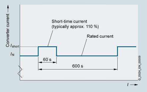
Overload capability of SINAMICS G180


 Ответ от производителя может занять до 5 дней и более.

