Standard interface Siemens
Обзор
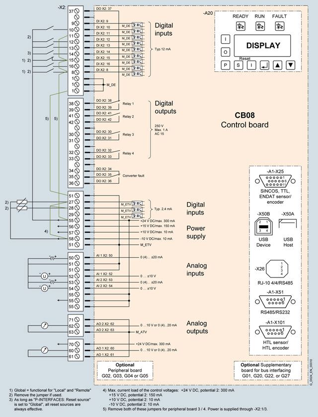
Standard assignment of inputs/outputs
The following table shows the default assignments of the interface for a "standard" application.
Signal designation | Function |
|---|---|
Digital input signals of module "CB08" | |
Internal digital input 8 | Controller enable global 1 |
Internal digital input 9 | Freely parameterizable |
Internal digital input 10 | Speed ON remote |
Internal digital input 11 | Freely parameterizable |
Internal digital input 12 | Local/remote, remote=1 |
Internal digital input 13 | External fault |
Internal digital input 14 | Remote reset |
Internal digital input 15 | Rapid stop global 1 |
Internal digital input 16 | Reverse remote |
Internal digital input 27 | PTC thermistor trip (not for explosion-proof motors) |
Internal digital input 28 | PTC thermistor prewarning (not for explosion-proof motors) |
Internal digital input 29 | External warning |
Digital output signals of module "CB08" | |
Internal digital output 37, 38, 39 | Relay 1: "Ready" |
Internal digital output 41, 42 | Relay 2: "Operation" |
Internal digital output 30, 31 | Relay 3: "Alarm" |
Internal digital output 32, 33 | Relay 4: Not assigned |
Internal digital output 34, 35, 36 | "Converter fault" |
Analog input signals of module "CB08" | |
Internal analog input 50, 51, 52 | Speed setpoint |
Internal analog input 53, 54 | User-assignable connection |
Analog output signals of module "CB08" | |
Internal analog output 60, 61 | Motor speed |
Internal analog output 62, 63 | Motor current |
NAMUR-compliant assignment of inputs/outputs
The following table shows the default assignments of the interface for a "NAMUR" application.
Signal designation | Function |
|---|---|
Digital input signals of module "CB08" | |
Internal digital input 8 | Main contactor checkback |
Internal digital input 9 | Test/Normal switch on converter |
Internal digital input 10 | ON/OFF static; ON dynamic (controller enable ON) |
Internal digital input 11 | OFF dynamic (controller enable OFF) |
Internal digital input 12 | Fast (motorized potentiometer UP) |
Internal digital input 13 | Slow (motorized potentiometer DOWN) |
Internal digital input 14 | Reset normal |
Internal digital input 15 | Interlock (controller disable) |
Internal digital input 16 | Reverse normal |
Internal digital input 27 | Freely parameterizable |
Internal digital input 28 | Freely parameterizable |
Internal digital input 29 | Freely parameterizable |
Digital output signals of module "CB08" | |
Internal digital output 37, 38, 39 | Relay 1: "Group prewarning" |
Internal digital output 41, 42 | Relay 2: "Main(line)contactor closed" |
Internal digital output 30, 31 | Relay 3: "Ready" |
Internal digital output 32, 33 | Relay 4: "Motor turning" |
Internal digital output 34, 35, 36 | "Converter fault" |
Analog input signals of module "CB08" | |
Internal analog input 50, 51, 52 | Speed setpoint (terminal 50/51 or 52/51) |
Internal analog input 53, 54 | Actual process value/user-assignable input (terminal 53/51 or 54/51) |
Analog output signals of module "CB08" | |
Internal analog output 60, 61 | Motor speed |
Internal analog output 62, 63 | Motor current |


 Ответ от производителя может занять до 5 дней и более.

