Liquid-cooled units Siemens
Обзор
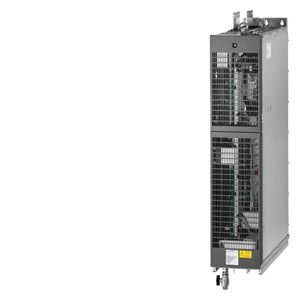
The SINAMICS S120 liquid-cooled drive units are specifically designed to address the requirements relating to liquid cooling; they are characterized by their high power density and optimized footprint. Liquid cooling dissipates heat much more efficiently than air cooling systems. As a result, liquid-cooled units are much more compact than air-cooled units with the same power rating. Since the power losses generated by the electronic components are almost completely dissipated by the liquid coolant, only very small cooling fans are required. This makes the drive units extremely quiet in operation. Due to their compact dimensions and almost negligible cooling air requirement, liquid-cooled units are the preferred solution wherever installation space is restricted and/or the ambient operating conditions are rough.
Control cabinets with liquid cooling are easy to implement as hermetically sealed units with degrees of protection of IP54 or higher.
The product portfolio includes the following liquid-cooled SINAMICS S120 chassis units:
- Ready-to-connect AC/AC units:
- Power Modules
- Infeed units:
- Basic Line Modules
- Active Line Modules
- Inverters (Motor Modules)
System components such as line reactors, Active Interface Modules, motor reactors and motor filters are air-cooled.
Highlights of the liquid-cooled units
- Up to a 60 % smaller footprint than air-cooled drive converters
- All main components such as power semiconductors, DC link capacitors and balancing resistors are cooled by the cooling circuit
- Only a low flow rate is required
- Uniform pressure drop of 0.7 bar
- Automatic protective functions
- Plated busbars
- Extremely quiet with < 56 dB
- Compatible with all components and functions and tools of the SINAMICS system family
- The power rating can be extended by connecting units in parallel
- No equipment fans
Cabinet units in liquid-cooled version
Liquid-cooled SINAMICS S120 drive units are also available as cabinet units, including cooling system. These are tailored to the specific requirements and represent a tailor-made, all-in-one solution for every drive task. You can obtain information about these units from your local Siemens office.
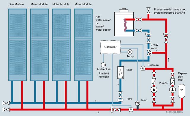
Example of a drive line-up with SINAMICS S120 liquid-cooled
Характеристика
Overload capability
SINAMICS S120 Liquid Cooled units have an overload reserve, e.g. to handle breakaway torques. If larger surge loads occur, this must be taken into account when configuring. In drives with overload requirements, the appropriate base load current must, therefore, be used as a basis for the required load.
The permissible overload levels are valid under the prerequisite that the drive units are operated with their base load current before and after the overload condition based on a duty cycle duration of 300 s.
For short, repeating load cycles with significant load fluctuations within the load cycle, the appropriate sections in the SINAMICS Low Voltage Engineering Manual must be observed (as PDF file on the CD-ROM provided with the catalog).
Power Modules and Motor Modules
The base load current for a low overload IL is the basis for a duty cycle of 110 % for 60 s or 150 % for 10 s.
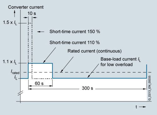
Low overload
The base load current for a high overload IH is the basis for a duty cycle of 150 % for 60 s or 160 % for 10 s.
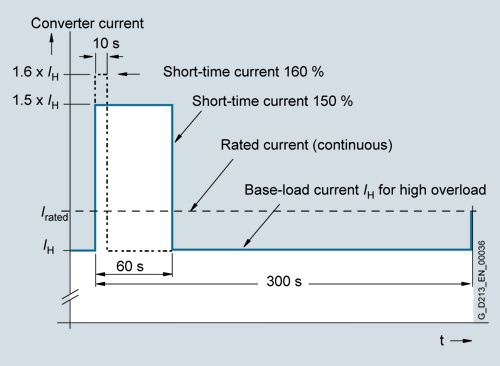
High overload
Line Modules
The base load current for a high overload IH DC is the basis for a duty cycle of 150 % for 60 s or Imax DC for 5 s.
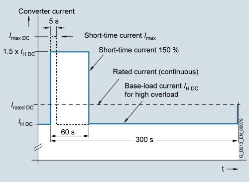
High overload
Pressure drop
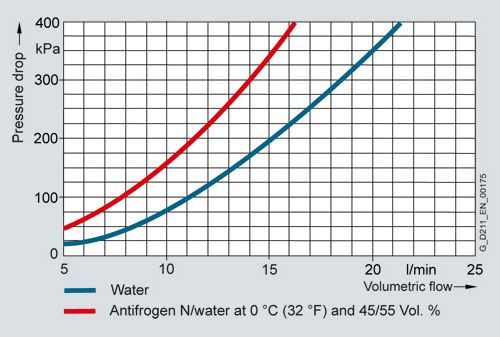
Pressure drop for frame size FL
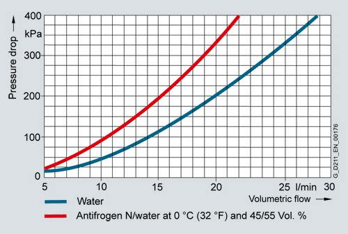
Pressure drop for frame size GL
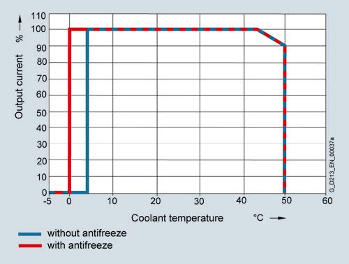
Current derating as a function of the temperature of the cooling liquid
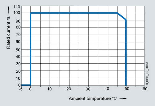
Current derating as a function of ambient temperature
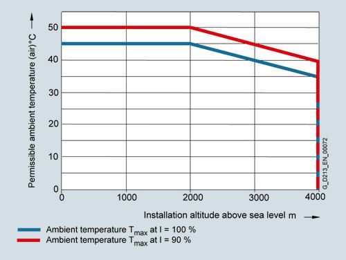
Permissible ambient temperature as a function of installation altitude
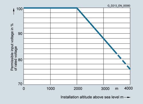
Voltage derating as a function of installation altitude
Технические данные
General technical specifications
Unless clearly specified otherwise, the following technical data are valid for all the following components of the liquid-cooled SINAMICS S120 drive system in the chassis format.
Electrical specifications | |
|---|---|
Rated voltages | 380 ... 480 V 3 AC, ±10 % (-15 % < 1 min) 500 ... 690 V 3 AC, ±10 % (-15 % < 1 min) |
Line supply types | Grounded TN/TT systems and non-grounded IT systems |
Line frequency | 47 ... 63 Hz |
Overvoltage category | III to EN 61800-5-1 |
Electronics power supply | 24 V DC, -15 % +20 % |
Rated short-circuit current SCCR (Short Circuit Current Rating) according to UL508C (up to 600 V), in conjunction with the specified fuses or circuit breakers Rated power | |
| 65 kA |
| 84 kA |
| 170 kA |
| 200 kA |
Control method | Vector/servo control with and without encoder or V/f control |
Fixed speeds | 15 fixed speeds plus 1 minimum speed, parameterizable (in the default setting, 3 fixed setpoints plus 1 minimum speed are selectable using terminal block/PROFIBUS/PROFINET) |
Skipped speed ranges | 4, parameterizable |
Setpoint resolution | 0.001 rpm digital (14 bits + sign) |
Braking operation | With Active Line Modules and Smart Line Modules, four-quadrant operation as standard (energy recovery). With Basic Line Modules, single-quadrant operation as standard. Braking when the power fails using an optional braking module. |
Mechanical specifications | ||
|---|---|---|
Degree of protection | IP00 or IP20 dependent on type | |
Protection class | I acc. to EN 61800-5-1 | |
Touch protection | EN 50274 / BGV A3 (for the intended purpose) | |
Type of cooling | Liquid cooling with integrated heat exchanger in aluminum or stainless steel version | |
Cooling circuit | ||
| 600 kPa | |
| 70 kPa | |
| 80 … 200 kPa | |
| Dependent on the ambient temperature, condensation is not permitted 0 … 45 °C without derating > 45 … 50 °C, see derating data Temperature range between 0 °C and 5 °C only with antifreeze (recommended antifreeze "Antifrogen N" from the Clariant company) | |
Coolant quality | for aluminum heat sinks | for stainless steel heat sinks |
| Deionized water with reduced conductivity (5 ... 10 μS/cm), e.g.:
| Filtered drinking water with the following quality: |
| < 40 mg/l, if required, achieved by adding deionized water | < 200 mg/l |
| < 50 mg/l | < 240 mg/l |
| < 50 mg/l | < 50 mg/l |
| 5.5 ... 8.0 | 6.5 ... 9.0 |
| < 500 μS/cm | < 2000 μS/cm |
| < 1.7 mmol/l | < 1.7 mmol/l |
| < 340 mg/l | < 340 mg/l |
| < 100 μm | < 100 μm |
The coolant definition specified here should only be considered as recommendation. For units that have been shipped, the information and data provided in the equipment manual supplied must be observed! | ||
A detailed description of the cooling circuits and the recommended coolant is given in the SINAMICS Low Voltage Engineering Manual on the CD-ROM provided with the catalog.
Ambient conditions | Storage 1) | Transport 1) | Operation |
|---|---|---|---|
Ambient temperature (air) | -40 ... +70 °C Class 1K3 | -40 ... +70 °C Class 2K4 | Line-side components, Power Modules, Line Modules and Motor Modules: 0 … 45 °C without derating Control Units, supplementary system components, DC link components and Sensor Modules 0 … 50 °C |
Relative humidity Condensation, splashwater, and ice formation not permitted (EN 60204, Part 1) | 5 ... 95 % Class 1K4 | max. 95 % at 40 °C Class 2K3 | 5 ... 95 % 2) Class 3K3 |
Environmental class/harmful chemical substances | Class 1C2 | Class 2C2 | Class 3C2 |
Organic/biological influences | Class 1B1 | Class 2B1 | Class 3B1 |
Degree of pollution | 2 acc. to EN 61800-5-1 | 2 acc. to EN 61800-5-1 | 2 acc. to EN 61800-5-1 |
Installation altitude | Up to 2000 m above sea level without derating | Up to 2000 m above sea level without derating | Up to 2000 m above sea level without derating |
Mechanical stability | Storage 1) | Transport 1) | Operation |
Vibration load |
| Class 2M2 | Test values
|
Shock load Class |
| Class 2M2 | Test values |
Compliance with standards | |||
Conformances/approvals, according to | CE (EMC Directive No. 2004/108/EC and Low-Voltage Directive No. 2006/95/EC) cULus (only for devices connected to line supply voltages 380 ... 480 V 3 AC and 500 ... 600 V 3 AC) | ||
Radio interference suppression | SINAMICS drive converter systems are not designed for connection to the public network (first environment). Radio interference suppression is compliant with the EMC product standard for variable-speed drives EN 61800-3, "Second environment" (industrial line supplies). The equipment can cause electromagnetic interference when it is connected to the public network. However, if supplementary measures are taken (e.g. → line filter), it can also be operated in the "first environment". | ||
1) In transport packaging.
2) Deviations with respect to the specified class are underlined.


 Ответ от производителя может занять до 5 дней и более.

