Power Modules Siemens
Обзор
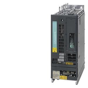
The Power Module comprises a line rectifier, a DC link and an inverter to supply the motor.
Power Modules are designed for drives that are not capable of regenerating energy to the mains supply. Regenerative energy produced while braking is converted to heat using braking resistors.
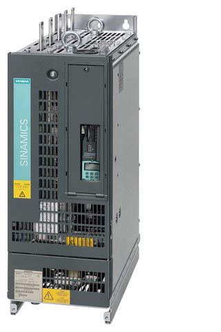
Liquid-cooled Power Modules are suitable for applications where space is restricted and for plants/machines that cannot be equipped with air-cooled units due to critical environmental conditions.
Дизайн
The liquid-cooled Power Modules have the following interfaces as standard:
- 1 line supply connection
- 1 DC link connection
- 3 DRIVE-CLiQ sockets
- 1 Safe stop input (enable pulses)
- 1 temperature sensor input (KTY84-130, PTC or Pt100)
- 1 connection for the 24 V DC electronics power supply
- 1 motor connection
- 2 PE/protective conductor connections
- 2 coolant connections
The CU310 Control Unit can be integrated into the liquid-cooled Power Modules.
The scope of supply of the Power Modules includes:
- 1 DRIVE-CLiQ cable for connection to the CU310 Control Unit
- 1 CD-ROM with Manual in the PDF format
- 2 seals for coolant connections
Интеграция
The Power Modules communicate with the higher-level control module via DRIVE-CLiQ. The control module in this case can be a CU310, CU320-2 or a SIMOTION D Control Unit. An external 24 V DC power supply is required to operate liquid-cooled Power Modules.
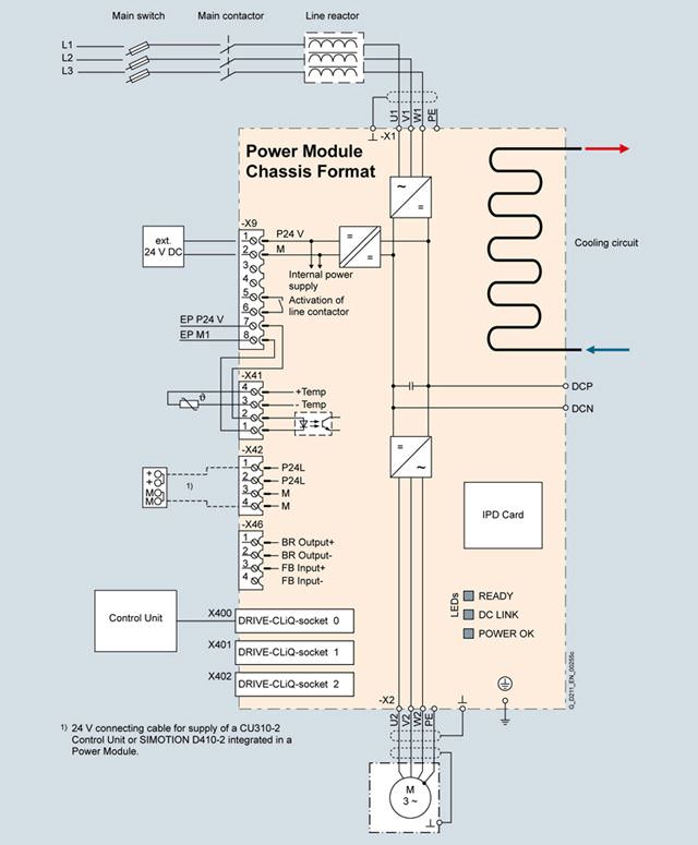
Connection example, liquid-cooled Power Module in the chassis format
Note:
The integrated 24 V power supply at connector X42 can have a maximum load of 2 A. When the Control Unit is supplied from the integrated power supply, the total load of the digital outputs must be carefully observed in order that the 2 A is not exceeded.
Технические данные
General technical specifications
Electrical specifications | |
|---|---|
Line supply voltage up to 2000 m above sea level | 380 … 480 V 3 AC ±10 % (-15 % < 1 min) |
Line power factor for a three-phase AC line supply voltage and rated power | |
| > 0.96 |
| 0.75 … 0.93 |
Efficiency | > 98 % |
DC link voltage, approx. | 1.35 × line voltage |
Output voltage, approx. | 0 ... 0.97 × Uline |
Output frequency 1) | |
| 0 … 650 Hz |
| 0 … 600 Hz |
| 0 … 600 Hz |
Electronics power supply | 24 V DC -15 %/+20 % |
Main contactor control | |
| 240 V AC, max. 8 A |
Conformity | CE (EMC Directive No. 2004/108/EC and Low-Voltage Directive No. 2006/95/EC) |
Approvals, according to | cULus |
Safety Integrated | Safety Integrity Level 2 (SIL2) acc. to IEC 61508, Performance Level d (PLd) acc. to EN ISO 13849-1 and Control Category 3 acc. to EN ISO 13849-1 (previously EN 954-1). |
1) Please note:
- The correlation between the maximum output frequency, pulse frequency and current derating. Higher output frequencies for specific configurations are available on request.
- The correlation between the minimum output frequency and permissible output current (current derating).
Information is provided in the SINAMICS Low Voltage Engineering Manual.
Line voltage 380 V … 480 V 3 AC | Power Modules | ||||
|---|---|---|---|---|---|
|
| 6SL3315-1TE32-1AA3 | 6SL3315-1TE32-6AA3 | 6SL3315-1TE33-1AA3 | 6SL3315-1TE35-0AA3 |
Type rating | |||||
| kW | 110 | 132 | 160 | 250 |
| kW | 90 | 110 | 132 | 200 |
| hp | 150 | 200 | 250 | 400 |
| hp | 150 | 200 | 200 | 350 |
Output current | |||||
| A | 210 | 260 | 310 | 490 |
| A | 205 | 250 | 302 | 477 |
| A | 178 | 233 | 277 | 438 |
| A | 307 | 375 | 453 | 715 |
Input current | |||||
| A | 230 | 285 | 340 | 540 |
| A | 336 | 411 | 496 | 788 |
Current demand | |||||
| A | 1.4 | 1.4 | 1.5 | 1.5 |
Pulse frequency 5) | |||||
| kHz | 2 | 2 | 2 | 2 |
| |||||
| kHz | 2 | 2 | 2 | 2 |
| kHz | 8 | 8 | 8 | 8 |
Power loss, at 50 Hz 400 V 6) | |||||
| kW | 2.36 | 2.97 | 3.31 | 5.29 |
| kW | 0.06 | 0.07 | 0.09 | 0.14 |
| kW | 2.42 | 3.04 | 3.4 | 5.43 |
Coolant flow rate 7) | l/min | 9 | 9 | 12 | 12 |
Volume of liquid in the integrated heat exchanger | dm3 | 0.52 | 0.52 | 0.88 | 0.88 |
Pressure drop, typ. 8) for volumetric flow | Pa | 70000 | 70000 | 70000 | 70000 |
Heat exchanger material |
| Stainless steel | Stainless steel | Stainless steel | Stainless steel |
Sound pressure level LpA (1 m) at 50/60 Hz | dB | 52 | 52 | 52 | 52 |
Line supply connection U1, V1, W1 |
| Hole for M12 | Hole for M12 | Hole for M12 | Hole for M12 |
| mm2 | 2 × 95 | 2 × 95 | 2 × 240 | 2 × 240 |
Motor connection U2/T1, V2/T2, W2/T3 |
| Hole for M12 | Hole for M12 | 2 × hole for M12 | 2 × hole for M12 |
| mm2 | 2 × 95 | 2 × 95 | 2 × 240 | 2 × 240 |
Cable length, max. 9) | |||||
| m | 300 | 300 | 300 | 300 |
| m | 450 | 450 | 450 | 450 |
PE/GND connection |
| 2 × hole for M12 | 2 × hole for M12 | 2 × hole for M12 | 2 × hole for M12 |
| mm2 | 2 × 95 | 2 × 95 | 2 × 240 | 2 × 240 |
Degree of protection |
| IP00 | IP00 | IP00 | IP00 |
Dimensions | |||||
| mm | 265 | 265 | 265 | 265 |
| mm | 836 | 836 | 983 | 983 |
| mm | 549 | 549 | 549 | 549 |
Weight, approx. | kg | 77 | 77 | 108 | 108 |
Frame size |
| FL | FL | GL | GL |
1) Rated power of a typ. 6-pole standard induction motor based on IL or IH with 400 V 3 AC 50 Hz.
2) Rated power of a typ. 6-pole standard induction motor based on IL or IH with 460 V 3 AC 60 Hz.
3) The base load current IL is the basis for a duty cycle of 110 % for 60 s or 150 % for 10 s with a duty cycle duration of 300 s.
4) The base load current IH is the basis for a duty cycle of 150 % for 60 s or 160 % for 10 s with a duty cycle duration of 300 s.
5)Information regarding the correlation between the pulse frequency and maximum output current/output frequency is provided in the SINAMICS Low Voltage Engineering Manual.
6) The specified power loss represents the maximum value at 100 % utilization. The value is lower under normal operating conditions.
7) The value applies to water and a mixture of water and Antifrogen N mixture with 45 % Antifrogen N as coolant.
8) The value is valid for water as coolant. Additional information and notes on other coolants is provided in the SINAMICS Low Voltage Engineering Manual.
9) Longer cable lengths for specific configurations are available on request. For additional information, please refer to the SINAMICS Low Voltage Engineering Manual.
Derating data
The following derating factors must be taken into account when using the units:
Liquid-cooled Power Module, chassis format | Rated output current | Derating factor at the pulse frequency | |
|---|---|---|---|
6SL3315-... | A | 2.5 kHz | 4 kHz |
1TE32-1AA3 | 210 | 0.95 | 0.82 |
1TE32-6AA3 | 260 | 0.95 | 0.83 |
1TE33-1AA3 | 310 | 0.97 | 0.88 |
1TE35-0AA3 | 490 | 0.94 | 0.78 |
Output current as a function of the pulse frequency


 Ответ от производителя может занять до 5 дней и более.

