Basic Line Modules Siemens
Обзор
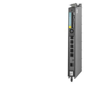
Basic Line Modules are used for applications where energy is not fed back into the line supply or where energy is exchanged in the DC link between axes operating in the motor and generator modes. The connected Motor Modules are pre-charged via the thyristor gate control. Basic Line Modules are designed for connection to grounded TN/TT and non-grounded IT supply systems.
Liquid-cooled Basic Line Modules are especially suitable for applications where installation space is restricted and for critical environmental conditions.
Дизайн
The liquid-cooled Basic Line Modules have the following interfaces as standard:
- 1 line supply connection
- 1 DC link connection (DCP, DCN) for supplying the connected Motor Modules
- 3 DRIVE-CLiQ sockets
- 1 temperature sensor input (KTY84-130, PTC or Pt100)
- 1 connection for the 24 V DC electronics power supply
- 1 PE/protective conductor connection
- 2 coolant connections
The scope of supply of the Power Modules includes:
- 1 DRIVE-CLiQ cable to connect to the CU320-2 or SIMOTION D4x5 Control Unit
- 1 CD-ROM with Manual in the PDF format
- 2 seals for coolant connections
Интеграция
The liquid-cooled Basic Line Modules communicate with the higher-level control module via DRIVE-CLiQ. The control module in this case can be a CU320-2 or a SIMOTION D Control Unit. An external 24 V DC power supply is required to operate liquid-cooled Basic Line Modules.
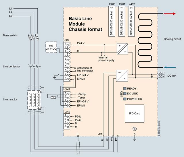
Connection example of a Basic Line Module
Технические данные
General technical specifications
Electrical specifications | |
|---|---|
Line power factor at rated power | |
| > 0.96 |
| 0.75 … 0.93 |
Efficiency | > 99 % |
DC link voltage, approx. 1) | 1.35 × line voltage |
Main contactor control | |
| 240 V AC, max. 8 A |
1) The DC link voltage is unregulated and load-dependent. For additional information, please refer to the SINAMICS Low Voltage Engineering Manual.
Line voltage 380 … 480 V 3 AC | Basic Line Modules | |||
|---|---|---|---|---|
|
| 6SL3335-1TE37-4AA3 | 6SL3335-1TE41-2AA3 | 6SL3335-1TE41-7AA3 |
Rated power | ||||
| kW | 360 | 600 | 830 |
| kW | 280 | 450 | 650 |
| hp | 555 | 925 | 1280 |
| hp | 430 | 690 | 1000 |
DC link current | ||||
| A | 740 | 1220 | 1730 |
| A | 578 | 936 | 1350 |
| A | 1110 | 1830 | 2595 |
Input current | ||||
| A | 610 | 1000 | 1420 |
| A | 915 | 1500 | 2130 |
Current demand | ||||
| A | 0.7 | 0.7 | 0.7 |
DC link capacitance | ||||
| μF | 12000 | 20300 | 26100 |
| μF | 96000 | 162400 | 208800 |
Power loss, | ||||
| kW | 2.66 | 4.32 | 5.78 |
| kW | 0.24 | 0.4 | 0.57 |
| kW | 2.9 | 4.72 | 6.35 |
Coolant flow rate 3) | l/min | 9 | 9 | 12 |
Volume of liquid in the integrated heat exchanger | dm3 | 0.45 | 0.45 | 0.79 |
Pressure drop, typ. 4) for volumetric flow | Pa | 70000 | 70000 | 70000 |
Heat exchanger material |
| Aluminum | Aluminum | Aluminum |
Sound pressure level LpA (1 m) at 50/60 Hz | dB | 54 | 56 | 56 |
Line supply connection U1, V1, W1 |
| 2 × M12 nut | 2 × M12 nut | 2 × M12 nut |
| mm2 | 4 × 240 | 4 × 240 | 4 × 240 |
DC link connection DCP, DCN |
| 2 × M12 nut Busbar | 2 × M12 nut Busbar | 2 × M12 nut Busbar |
PE/GND connection |
| 2 × M12 nut | 2 × M12 nut | 2 × M12 nut |
| mm2 | 4 × 240 | 4 × 240 | 4 × 240 |
Cable length, max. 5) | ||||
| m | 2600 | 4000 | 4800 |
| m | 3900 | 6000 | 7200 |
Degree of protection |
| IP00 | IP00 | IP00 |
Dimensions | ||||
| mm | 160 | 160 | 160 |
| mm | 1137 | 1137 | 1562 |
| mm | 545 | 545 | 545 |
Weight, approx. | kg | 108 | 108 | 185 |
Frame size |
| FBL | FBL | GBL |
1) The base load current IH DC is the basis for a duty cycle of 150 % for 60 s or Imax DC for 5 s with a duty cycle duration of 300 s.
2) The specified power loss represents the maximum value at 100 % utilization. The value is lower under normal operating conditions.
3) The value applies to water and a mixture of water and Antifrogen N mixture with 45 % Antifrogen N as coolant.
4) The value is valid for water as coolant. Additional information and notes on other coolants is provided in the SINAMICS Low Voltage Engineering Manual.
5) Sum of all motor cables and DC link. Longer cable lengths for specific configurations are available on request. For additional information, please refer to the SINAMICS Low Voltage Engineering Manual.
Line voltage 500 … 690 V 3 AC | Basic Line Module | ||||
|---|---|---|---|---|---|
|
| 6SL3335-1TG34-2AA3 | 6SL3335-1TG37-3AA3 | 6SL3335-1TG41-3AA3 | 6SL3335-1TG41-7AA3 |
Rated power | |||||
| kW | 355 | 630 | 1100 | 1370 |
| kW | 275 | 475 | 840 | 1070 |
| kW | 245 | 420 | 750 | 950 |
| kW | 200 | 345 | 610 | 775 |
| hp | 395 | 705 | 1230 | 1530 |
| hp | 305 | 530 | 940 | 1195 |
DC link current | |||||
| A | 420 | 730 | 1300 | 1650 |
| A | 328 | 570 | 1014 | 1287 |
| A | 630 | 1095 | 1950 | 2475 |
Input current | |||||
| A | 340 | 600 | 1070 | 1350 |
| A | 510 | 900 | 1605 | 2025 |
Current demand | |||||
| A | 0.7 | 0.7 | 0.7 | 0.7 |
DC link capacitance | |||||
| μF | 4800 | 7700 | 15500 | 19300 |
| μF | 38400 | 61600 | 124000 | 154400 |
Power loss, at 50 Hz 500/690 V 2) | |||||
| kW | 1.48/1.54 | 2.65/2.71 | 4.55/4.66 | 5.6/5.7 |
| kW | 0.22 | 0.38 | 0.43 | 0.54 |
| kW | 1.7/1.76 | 3.03/3.09 | 4.98/5.09 | 6.14/6.24 |
Coolant flow rate | l/min | 9 | 9 | 12 | 12 |
Volume of liquid in the integrated heat exchanger | dm3 | 0.45 | 0.45 | 0.79 | 0.79 |
Pressure drop, typ. 4) for volumetric flow | Pa | 70000 | 70000 | 70000 | 70000 |
Heat exchanger material |
| Aluminum | Aluminum | Aluminum | Aluminum |
Sound pressure level LpA (1 m) at 50/60 Hz | dB | 54 | 54 | 56 | 56 |
Line supply connection U1, V1, W1 |
| 2 × M12 nut | 2 × M12 nut | 2 × M12 nut | 2 × M12 nut |
| mm2 | 4 × 240 | 4 × 240 | 4 × 240 | 4 × 240 |
DC link connection DCP, DCN |
| 2 × M12 nut Busbar | 2 × M12 nut Busbar | 2 × M12 nut Busbar | 2 × M12 nut Busbar |
PE/GND connection |
| 2 × M12 nut | 2 × M12 nut | 2 × M12 nut | 2 × M12 nut |
|
| 4 × 240 | 4 × 240 | 4 × 240 | 4 × 240 |
Cable length, max. 5) | |||||
| m | 1500 | 1500 | 2250 | 2250 |
| m | 2250 | 2250 | 3375 | 3375 |
Degree of protection |
| IP00 | IP00 | IP00 | IP00 |
Dimensions | |||||
| mm | 160 | 160 | 160 | 160 |
| mm | 1137 | 1137 | 1562 | 1562 |
| mm | 545 | 545 | 545 | 545 |
Weight, approx. | kg | 108 | 108 | 185 | 185 |
Frame size |
| FBL | FBL | GBL | GBL |
1) The base load current IH DC is the basis for a duty cycle of 150 % for 60 s or Imax DC for 5 s with a duty cycle duration of 300 s.
2) The specified power loss represents the maximum value at 100 % utilization. The value is lower under normal operating conditions.
3) The value applies to water and a mixture of water and Antifrogen N mixture with 45 % Antifrogen N as coolant.
4) The value is valid for water as coolant. Additional information and notes on other coolants is provided in the SINAMICS Low Voltage Engineering Manual.
5) Sum of all motor cables and DC link. Longer cable lengths for specific configurations are available on request. For additional information, please refer to the SINAMICS Low Voltage Engineering Manual.


 Ответ от производителя может занять до 5 дней и более.

