Active Line Modules Siemens
Обзор
The self-commutated infeed/regenerative feedback units (with IGBTs in infeed and regenerative feedback directions) generate a regulated DC link voltage. This means that the connected Motor Modules are decoupled from the line voltage. Line voltage fluctuations within the permissible supply tolerances have no effect on the motor voltage.
If required, the Active Line Modules can also provide reactive power compensation.
Active Line Modules are designed for connection to grounded TN/TT and non-grounded IT supply systems.
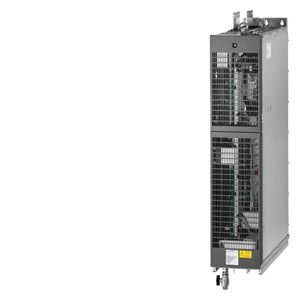
Liquid-cooled Active Line Modules are especially suitable for applications where installation space is restricted and for critical environmental conditions.
Active Line Modules are always operated together with the associated Active Interface Modules. These include the necessary pre-charging circuit as well as a Clean Power Filter.
System components such as line reactors, Active Interface Modules, motor reactors and motor filters are air-cooled.
See also selection and ordering data in the section Chassis Format, air-cooled → Active Interface Module.
Дизайн
The liquid-cooled Active Line Modules have the following interfaces as standard:
- 1 line supply connection
- 1 connection for the 24 V DC electronics power supply
- 1 DC link connection (DCP, DCN) for supplying the connected Motor Modules
- 3 DRIVE-CLiQ sockets
- 1 temperature sensor input (KTY84-130, PTC or Pt100)
- 1 PE/protective conductor connection
- 2 coolant connections
The following are included in the scope of supply of the Active Line Modules:
- 1 DRIVE-CLiQ cable to connect to the CU320-2 or SIMOTION D4x5 Control Unit
- 1 CD-ROM with Manual in PDF format
- 2 seals for coolant connections
Интеграция
Active Line Modules are always operated together with the associated Active Interface Modules. Active Interface Modules contain a Clean Power Filter with basic RI suppression, the precharging circuit for the Active Line Module, line supply voltage sensing circuit and monitoring sensors.
The liquid-cooled Active Line Modules communicate with the higher-level control module via DRIVE-CLiQ. The control module in this case can be a CU320-2 or a SIMOTION D Control Unit. An external 24 V DC power supply is required to operate the Active Line Modules.
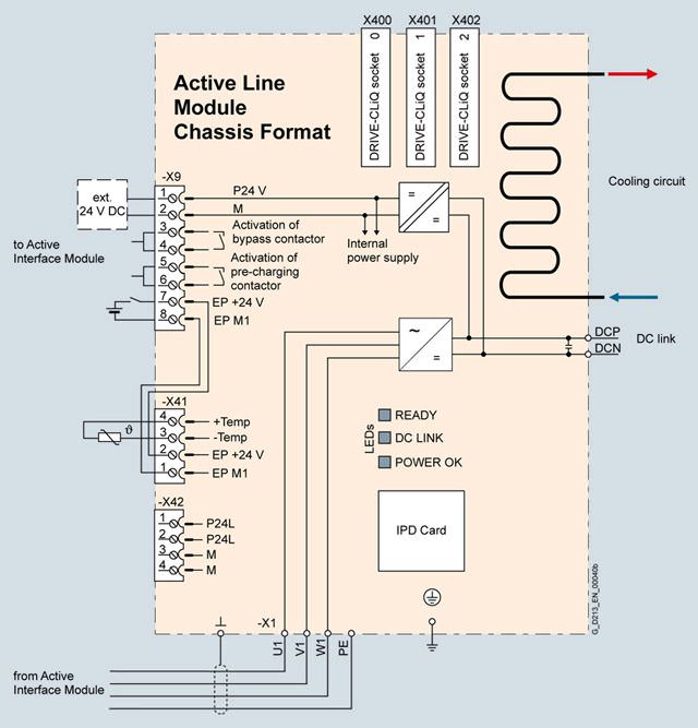
Connection example of an Active Line Module
Технические данные
General technical specifications
Electrical specifications | |
|---|---|
Line power factor | |
| 1.0 (factory setting), can be altered by input of a reactive current setpoint |
| 1.0 (factory setting) |
Efficiency | > 98.5 % (ALM) > 99 % (AIM) |
DC link voltage, approx. | The DC link voltage is regulated and can be adjusted as a voltage decoupled from the line voltage. |
Conformity | CE (EMC Directive No. 2004/108/EC and Low-Voltage Directive No. 2006/95/EC) |
Approvals, according to | cULus (only for drive units connected to line voltages 380 ... 480 V 3 AC and 500 ... 600 V 3 AC) |
Safety Integrated | Safety Integrity Level 2 (SIL2) acc. to IEC 61508, Performance Level d (PLd) acc. to EN ISO 13849-1 and Control Category 3 acc. to EN ISO 13849-1 (previously EN 954-1). |
Line voltage 380 V … 480 V 3 AC | Active Line Modules | ||
|---|---|---|---|
|
| 6SL3335-7TE35-0AA3 | 6SL3335-7TE38-4AA3 |
Rated power | |||
| kW | 300 | 500 |
| kW | 270 | 465 |
| hp | 500 | 700 |
| hp | 400 | 700 |
DC link current | |||
| A | 549 | 941 |
| A | 489 | 837 |
| A | 823 | 1410 |
Infeed/regenerative feedback current | |||
| A | 490 | 840 |
| A | 735 | 1260 |
Current demand | |||
| A | 1.5 | 1.6 |
DC link capacitance | |||
| μF | 9600 | 17400 |
Power loss, at 50 Hz 400 V 2) | |||
| kW | 3.1 | 5.52 |
| kW | 0.14 | 0.23 |
| kW | 3.24 | 5.75 |
Coolant flow rate 3) | l/min | 12 | 16 |
Volume of liquid in the integrated heat exchanger | dm3 | 0.91 | 0.74 |
Pressure drop, typ. 4) for volumetric flow | Pa | 70000 | 70000 |
Heat exchanger material |
| Stainless steel | Aluminum |
Sound pressure level LpA 5) (1 m) at 50/60 Hz | dB | 52 | 54 |
Line supply connection U1, V1, W1 |
| Hole for M12 | 2 x hole for M12 |
| mm2 | 2 × 240 | 4 × 185 |
DC link connection DCP, DCN |
| 2 x hole for M12 Busbar | 2 x hole for M12 Busbar |
PE/GND connection |
| 2 x hole for M12 | 2 x hole for M12 |
| mm2 | 2 × 240 | 4 × 185 |
Cable length, max. 6) | |||
| m | 2700 | 3900 |
| m | 4050 | 5850 |
Degree of protection |
| IP00 | IP00 |
Dimensions | |||
| mm | 150 | 265 |
| mm | 1172 | 1002 |
| mm | 545 | 545 |
Weight, approx. | kg | 80 | 110 |
Frame size |
| GXL | HXL |
1) The base load current IH DC is the basis for a duty cycle of 150 % for 60 s or Imax DC for 5 s with a duty cycle duration of 300 s.
2) The specified power loss represents the maximum value at 100 % utilization. The value is lower under normal operating conditions.
3) The value applies to water and a mixture of water and Antifrogen N mixture with 45 % Antifrogen N as coolant.
4) The value is valid for water as coolant. Additional information and notes on other coolants is provided in the SINAMICS Low Voltage Engineering Manual.
5) Total sound pressure level of Active Interface Module and Active Line Module.
6) Sum of all motor cables and DC link. Longer cable lengths for specific configurations are available on request. For additional information, please refer to the SINAMICS Low Voltage Engineering Manual.
Line voltage 500 V … 690 V 3 AC | Active Line Modules | ||
|---|---|---|---|
|
| 6SL3335-7TG35-8AA3 | 6SL3335-7TG41-3AA3 |
Rated power | |||
| kW | 560 | 1400 |
| kW | 550 | 1215 |
| kW | 435 | 965 |
| kW | 400 | 880 |
| hp | 600 | 1500 |
| hp | 450 | 1250 |
DC link current | |||
| A | 644 | 1422 |
| A | 573 | 1266 |
| A | 966 | 2133 |
Infeed/regenerative feedback current | |||
| A | 575 | 1270 |
| A | 862 | 1905 |
Current demand | |||
| A | 1.6 | 1.46 |
DC link capacitance | |||
| μF | 9670 | 19330 |
Power loss, at 50 Hz 500/690 V 2) | |||
| kW | 4.0/5.45 | 9.36/12.92 |
| kW | 0.16 | 0.57 |
| kW | 4.16/5.61 | 9.93/13.49 |
Coolant flow rate | l/min | 16 | 27 |
Volume of liquid in the integrated heat exchanger | dm3 | 0.74 | 1.56 |
Pressure drop, typ. 4) for volumetric flow | Pa | 70000 | 70000 |
Heat exchanger material |
| Aluminum | Aluminum |
Sound pressure level LpA 5) (1 m) at 50/60 Hz | dB | 54 | 56 |
Line supply connection U1, V1, W1 |
| 2 × hole for M12 | 2 × hole for M12 |
| mm2 | 4 × 185 | Busbar |
DC link connection DCP, DCN |
| 2 × hole for M12 Busbar | 2 × hole for M12 Busbar |
PE/GND connection |
| 2 × hole for M12 | 2 × hole for M12 |
| mm2 | 4 × 185 | Busbar |
Cable length, max. 6) | |||
| m | 2250 | 2250 |
| m | 3375 | 3375 |
Degree of protection |
| IP00 | IP00 |
Dimensions | |||
| mm | 265 | 295 |
| mm | 1002 | 1516 |
| mm | 545 | 545 |
Weight, approx. | kg | 110 | 220 |
Frame size |
| HXL | JXL |
1) The base load current IH DC is the basis for a duty cycle of 150 % for 60 s or Imax DC for 5 s with a duty cycle duration of 300 s.
2) The specified power loss represents the maximum value at 100 % utilization. The value is lower under normal operating conditions.
3) The value applies to water and a mixture of water and Antifrogen N mixture with 45 % Antifrogen N as coolant.
4) The value is valid for water as coolant. Additional information and notes on other coolants is provided in the SINAMICS Low Voltage Engineering Manual.
5) Total sound pressure level of Active Interface Module and Active Line Module.
6) Sum of all motor cables and DC link. Longer cable lengths for specific configurations are available on request. For additional information, please refer to the SINAMICS Low Voltage Engineering Manual.


 Ответ от производителя может занять до 5 дней и более.

