Motor Modules Siemens
Обзор
A Motor Module comprises a self-commutated inverter with IGBTs. It generates a variable voltage with variable frequency from the DC link voltage that feeds the connected motor.
Several Motor Modules can be interconnected through a common DC bus. This makes it possible to exchange energy between the Motor Modules. This means that if a Motor Module is in the generator mode, this energy can be used by another Motor Module operating in the motor mode.
Motor Modules are controlled by a Control Unit.
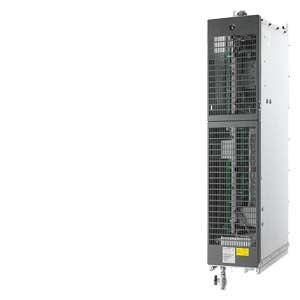
Liquid-cooled Motor Modules are available for applications where installation space is restricted and for plants or machines that cannot be equipped with air-cooled drive units as a result of critical environmental conditions.
Дизайн
The liquid-cooled Motor Modules have the following interfaces as standard:
- 1 motor connection
- 1 DC link connection (DCP, DCN) for connecting to the supply DC busbar
- 1 connection for Safety Integrated
- 1 temperature sensor input (KTY84-130, PTC or Pt100)
- 3 DRIVE-CLiQ sockets
- 1 connection for the 24 V DC electronics power supply
- 2 PE/protective conductor connections
- 2 coolant connections
The scope of supply of the Motor Modules includes:
- 1 DRIVE-CLiQ cable to connect to the CU320-2 or SIMOTION D4x5 Control Unit
- 1 CD-ROM with Manual in PDF format
- 2 seals for coolant connections
Интеграция
The liquid-cooled Motor Modules communicate with the higher-level control module via DRIVE-CLiQ. The control module in this case can be a CU320-2 or a SIMOTION D Control Unit.
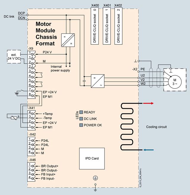
Connection example of a liquid-cooled Motor Module
Технические данные
General technical specifications
Electrical specifications | |
|---|---|
DC link voltage (up to 2000 m above sea level) | 510 ... 720 V DC (line supply voltage 380 ... 480 V 3 AC) or |
Efficiency | > 98.5 % |
Output frequency 1) | |
| 0 … 650 Hz |
| 0 … 600 Hz |
| 0 … 600 Hz |
Conformity | CE (EMC Directive No. 2004/108/EC and Low-Voltage Directive No. 2006/95/EC) |
Approvals, according to | cULus (only for drive units connected to line voltages 380 ... 480 V 3 AC and 500 ... 600 V 3 AC) |
Safety Integrated | Safety Integrity Level 2 (SIL2) acc. to IEC 61508, Performance Level d (PLd) acc. to EN ISO 13849-1 and Control Category 3 acc. to EN ISO 13849-1 (previously EN 954-1). |
1) Please note:
- The correlation between the maximum output frequency, pulse frequency and current derating. Higher output frequencies for specific configurations are available on request.
- The correlation between the minimum output frequency and permissible output current (current derating).
Information is provided in the SINAMICS Low Voltage Engineering Manual.
Line voltage 380 … 480 V 3 AC | Motor Modules | ||||
|---|---|---|---|---|---|
| 6SL3325-1TE32-1AA3 | 6SL3325-1TE32-6AA3 | 6SL3325-1TE33-1AA3 | 6SL3325-1TE35-0AA3 | |
Type rating | |||||
| kW | 110 | 132 | 160 | 250 |
| kW | 90 | 110 | 132 | 200 |
| hp | 150 | 200 | 250 | 400 |
| hp | 150 | 200 | 200 | 350 |
Output current | |||||
| A | 210 | 260 | 310 | 490 |
| A | 205 | 250 | 302 | 477 |
| A | 178 | 233 | 277 | 438 |
| A | 307 | 375 | 453 | 715 |
DC link current | |||||
| |||||
| A | 256 | 317 | 380 | 600 |
| A | 230 | 287 | 340 | 538 |
| |||||
| A | 250 | 305 | 368 | 581 |
| A | 225 | 274 | 331 | 522 |
| |||||
| A | 227 | 284 | 338 | 534 |
| A | 195 | 255 | 303 | 480 |
Current demand | |||||
| A | 1.4 | 1.4 | 1.5 | 1.5 |
DC link capacitance | μF | 4800 | 5800 | 8400 | 9600 |
Pulse frequency 5) | |||||
| kHz | 2 | 2 | 2 | 2 |
| |||||
| kHz | 2 | 2 | 2 | 2 |
| kHz | 8 | 8 | 8 | 8 |
Power loss, at 50 Hz 400 V 6) | |||||
| kW | 1.55 | 1.88 | 2.2 | 3.42 |
| kW | 0.06 | 0.07 | 0.09 | 0.14 |
| kW | 1.61 | 1.95 | 2.29 | 3.56 |
Coolant flow rate 7) | l/min | 9 | 9 | 12 | 12 |
Volume of liquid in the integrated heat exchanger | dm3 | 0.31 | 0.31 | 0.91 | 0.91 |
Pressure drop, typ. 8) for volumetric flow | Pa | 70000 | 70000 | 70000 | 70000 |
Heat exchanger material |
| Stainless steel | Stainless steel | Stainless steel | Stainless steel |
Sound pressure level LpA (1 m) at 50/60 Hz | dB | 52 | 52 | 52 | 52 |
DC link connection DCP, DCN |
| 2 × hole for M12 Busbar | 2 × hole for M12 Busbar | 2 × hole for M12 Busbar | 2 × hole for M12 Busbar |
Motor connection U2, V2, W2 |
| Hole for M12 | Hole for M12 | Hole for M12 | Hole for M12 |
| mm2 | 2 × 95 | 2 × 95 | 2 × 240 | 2 × 240 |
Cable length, max. 9) | |||||
| m | 300 | 300 | 300 | 300 |
| m | 450 | 450 | 450 | 450 |
PE/GND connection |
| 2 × hole for M12 | 2 × hole for M12 | 2 × hole for M12 | 2 × hole for M12 |
| mm2 | 2 × 95 | 2 × 95 | 2 × 240 | 2 × 240 |
Degree of protection |
| IP00 | IP00 | IP00 | IP00 |
Dimensions | |||||
| mm | 150 | 150 | 150 | 150 |
| mm | 746 | 746 | 1172 | 1172 |
| mm | 545 | 545 | 545 | 545 |
Weight, approx. | kg | 41 | 41 | 80 | 80 |
Frame size |
| FXL | FXL | GXL | GXL |
1) Rated power of a typ. 6-pole standard induction motor based on IL or IH with 400 V 3 AC 50 Hz.
2) Rated power of a typ. 6-pole standard induction motor based on IL or IH with 460 V 3 AC 60 Hz.
3) The base load current IL is the basis for a duty cycle of 110 % for 60 s or 150 % for 10 s with a duty cycle duration of 300 s.
4) The base load current IH is the basis for a duty cycle of 150 % for 60 s or 160 % for 10 s with a duty cycle duration of 300 s.
5)Additional notes regarding the correlation between the pulse frequency and maximum output current/output frequency is provided in the SINAMICS Low Voltage Engineering Manual.
6) The specified power loss represents the maximum value at 100 % utilization. The value is lower under normal operating conditions.
7) The value applies to water and a mixture of water and Antifrogen N mixture with 45 % Antifrogen N as coolant.
8) The value is valid for water as coolant. Additional information and notes on other coolants is provided in the SINAMICS Low Voltage Engineering Manual.
9) Sum of all motor cables. Longer cable lengths for specific configurations are available on request. For additional information, please refer to the SINAMICS Low Voltage Engineering Manual.
Line voltage 380 … 480 V 3 AC | Motor Modules | ||||
|---|---|---|---|---|---|
| 6SL3325-1TE36-1AA3 | 6SL3325-1TE38-4AA3 | 6SL3325-1TE41-0AA3 | 6SL3325-1TE41-4AA3 | |
Type rating | |||||
| kW | 315 | 450 | 560 | 800 |
| kW | 250 | 400 | 450 | 710 |
| hp | 500 | 700 | 800 | 1000 |
| hp | 350 | 600 | 700 | 1000 |
Output current | |||||
| A | 605 | 840 | 985 | 1405 |
| A | 590 | 820 | 960 | 1370 |
| A | 460 | 700 | 860 | 1257 |
| A | 885 | 1230 | 1440 | 2055 |
DC link current | |||||
| |||||
| A | 738 | 1025 | 1202 | 1714 |
| A | 664 | 922 | 1080 | 1544 |
| |||||
| A | 719 | 1000 | 1170 | 1670 |
| A | 646 | 898 | 1051 | 1500 |
| |||||
| A | 561 | 853 | 1048 | 1532 |
| A | 504 | 767 | 942 | 1377 |
Current demand | |||||
| A | 1.6 | 1.6 | 1.46 | 1.46 |
DC link capacitance | μF | 12600 | 17400 | 21000 | 29000 |
Pulse frequency 5) | |||||
| kHz | 1.25 | 1.25 | 1.25 | 1.25 |
| |||||
| kHz | 1.25 | 1.25 | 1.25 | 1.25 |
| kHz | 7.5 | 7.5 | 7.5 | 7.5 |
Power loss, at 50 Hz 400 V 6) | |||||
| kW | 4.65 | 5.52 | 7.46 | 9.53 |
| kW | 0.16 | 0.23 | 0.48 | 0.62 |
| kW | 4.81 | 5.75 | 7.94 | 10.15 |
Coolant flow rate 7) | l/min | 16 | 16 | 27 | 27 |
Volume of liquid in the integrated heat exchanger | dm3 | 0.74 | 0.74 | 1.56 | 1.56 |
Pressure drop, typ. 8) for volumetric flow | Pa | 70000 | 70000 | 70000 | 70000 |
Heat exchanger material |
| Aluminum | Aluminum | Aluminum | Aluminum |
Sound pressure level LpA (1 m) at 50/60 Hz | dB | 54 | 54 | 56 | 56 |
DC link connection DCP, DCN |
| 2 × hole for M12 Busbar | 2 × hole for M12 Busbar | 2 × hole for M12 Busbar | 2 × hole for M12 Busbar |
Motor connection U2, V2, W2 |
| 2 × hole for M12 | 2 × hole for M12 | 2 × hole for M12 | 2 × hole for M12 |
| mm2 | 4 × 185 | 4 × 185 | 4 × 240 | 4 × 240 |
Cable length, max. 9) | |||||
| m | 300 | 300 | 300 | 300 |
| m | 450 | 450 | 450 | 450 |
PE/GND connection |
| 2 × hole for M12 | 2 × hole for M12 | 2 × hole for M12 | 2 × hole for M12 |
| mm2 | 4 × 185 | 4 × 185 | Busbar | Busbar |
Degree of protection |
| IP00 | IP00 | IP00 | IP00 |
Dimensions | |||||
| mm | 265 | 265 | 295 | 295 |
| mm | 1002 | 1002 | 1516 | 1516 |
| mm | 545 | 545 | 545 | 545 |
Weight, approx. | kg | 110 | 110 | 220 | 220 |
Frame size |
| HXL | HXL | JXL | JXL |
1) Rated power of a typ. 6-pole standard induction motor based on IL or IH with 400 V 3 AC 50 Hz.
2) Rated power of a typ. 6-pole standard induction motor based on IL or IH with 460 V 3 AC 60 Hz.
3) The base load current IL is the basis for a duty cycle of 110 % for 60 s or 150 % for 10 s with a duty cycle duration of 300 s.
4) The base load current IH is the basis for a duty cycle of 150 % for 60 s or 160 % for 10 s with a duty cycle duration of 300 s.
5)Additional notes regarding the correlation between the pulse frequency and maximum output current/output frequency is provided in the SINAMICS Low Voltage Engineering Manual.
6) The specified power loss represents the maximum value at 100 % utilization. The value is lower under normal operating conditions.
7) The value applies to water and a mixture of water and Antifrogen N mixture with 45 % Antifrogen N as coolant.
8) The value is valid for water as coolant. Additional information and notes on other coolants is provided in the SINAMICS Low Voltage Engineering Manual.
9) Sum of all motor cables. Longer cable lengths for specific configurations are available on request. For additional information, please refer to the SINAMICS Low Voltage Engineering Manual.
Line voltage 500 … 690 V 3 AC | Motor Modules | ||||
|---|---|---|---|---|---|
| 6SL3325-1TG31-0AA3 | 6SL3325-1TG31-5AA3 | 6SL3325-1TG32-2AA3 | 6SL3325-1TG33-3AA3 | |
Rated power | |||||
| kW | 90 | 132 | 200 | 315 |
| kW | 75 | 110 | 160 | 250 |
| kW | 55 | 90 | 132 | 200 |
| kW | 55 | 90 | 132 | 200 |
| hp | 75 | 150 | 200 | 300 |
| hp | 75 | 125 | 200 | 250 |
Output current | |||||
| A | 100 | 150 | 215 | 330 |
| A | 95 | 142 | 208 | 320 |
| A | 89 | 134 | 192 | 280 |
| A | 142 | 213 | 312 | 480 |
DC link current | |||||
| |||||
| A | 122 | 183 | 263 | 403 |
| A | 110 | 165 | 237 | 363 |
| |||||
| A | 116 | 173 | 253 | 390 |
| A | 105 | 156 | 229 | 352 |
| |||||
| A | 108 | 163 | 234 | 341 |
| A | 98 | 147 | 211 | 308 |
Current demand | |||||
| A | 1.0 | 1.0 | 1.5 | 1.5 |
DC link capacitance | μF | 2800 | 2800 | 4200 | 5800 |
Pulse frequency 5) | |||||
| kHz | 1.25 | 1.25 | 1.25 | 1.25 |
| |||||
| kHz | 1.25 | 1.25 | 1.25 | 1.25 |
| kHz | 7.5 | 7.5 | 7.5 | 7.5 |
Power loss, at 50 Hz 500/690 V 6) | |||||
| kW | 0.8/1.09 | 1.15/1.57 | 1.65/2.25 | 2.4/3.27 |
| kW | 0.06 | 0.07 | 0.09 | 0.11 |
| kW | 0.86/1.15 | 1.22/1.64 | 1.74/2.34 | 2.51/3.38 |
Coolant flow rate 7) | l/min | 9 | 9 | 12 | 12 |
Volume of liquid in the integrated heat exchanger | dm3 | 0.31 | 0.31 | 0.91 | 0.91 |
Pressure drop, typ. 8) for volumetric flow | Pa | 70000 | 70000 | 70000 | 70000 |
Heat exchanger material |
| Stainless steel | Stainless steel | Stainless steel | Stainless steel |
Sound pressure level LpA (1 m) at 50/60 Hz | dB | 52 | 52 | 52 | 52 |
DC link connection DCP, DCN |
| 2 × hole for M12 Busbar | 2 × hole for M12 Busbar | 2 × hole for M12 Busbar | 2 × hole for M12 Busbar |
Motor connection U2, V2, W2 |
| Hole for M12 | Hole for M12 | Hole for M12 | Hole for M12 |
| mm2 | 2 × 95 | 2 × 95 | 4 × 240 | 4 × 240 |
Cable length, max. 9) | |||||
| |||||


 Ответ от производителя может занять до 5 дней и более.

