Braking Modules Siemens

Обзор
A Braking Module and the matching external braking resistor are required to bring drives to a controlled standstill in the event of a power failure (e.g. with an EMERGENCY STOP) or to limit the DC link voltage for brief periods of regenerative operation, e.g. if the Line Module is not capable of energy recovery.
The Braking Module includes the power electronics and the associated control circuit. During operation, the DC link energy is converted to heat loss in an external braking resistor.
The Braking Module works autonomously from the converter control.
Several Braking Modules can be operated in parallel, but a separate braking resistor must be connected to each Braking Module.
Braking Modules are designed to be integrated into air-cooled Motor Modules, Line Modules or Power Modules and are cooled by the fans on these modules. The supply voltage for the electronics is taken from the DC link. The Braking Modules are connected to the DC link by means of the busbar sets included in the scope of supply or flexible cables and, in the case of Basic Line Modules of frame size GB, using a separate cable harness set.
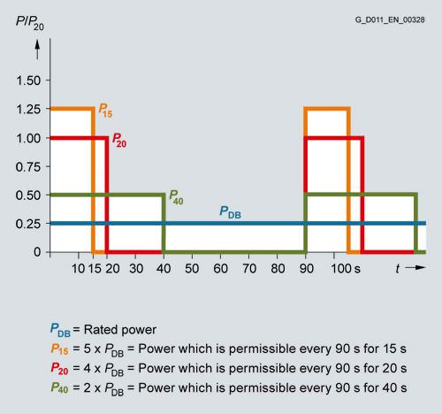
The activation threshold of the Braking Module can be adjusted by means of a DIP switch. The braking power values specified in the technical specifications apply to the upper activation threshold.
Дизайн
The Braking Modules have the following interfaces as standard:
- 1 DC link connection
- 1 braking resistor connection
- 1 digital input (inhibit Braking Module/acknowledge error)
- 1 digital output (Braking Module inhibited)
- 1 DIP switch for adjusting the activation threshold
Information about Braking Module activation thresholds and other notes are included in the SINAMICS Low Voltage Engineering Manual.
Характеристика
Connection example of a Braking Module
Интеграция
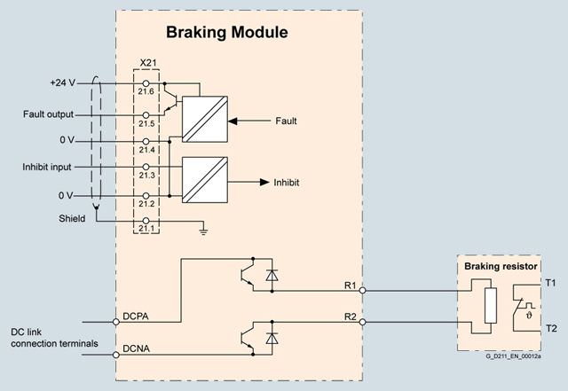
Connection example of a Braking Module
Технические данные
Line voltage 380 … 480 V 3 AC | Braking Module | |||
|---|---|---|---|---|
| 6SL3300-1AE31-3AA0 | 6SL3300-1AE32-5AA0 | 6SL3300-1AE32-5BA0 | |
Power | ||||
| kW | 25 | 50 | 50 |
| kW | 125 | 250 | 250 |
| kW | 100 | 200 | 200 |
| kW | 50 | 100 | 100 |
Activation thresholds (adjustable via DIP switch) | V | 774 (factory setting) or 673 | 774 (factory setting) or 673 | 774 (factory setting) or 673 |
Digital inputs In accordance with IEC 61131‑2 Type 1 | ||||
| V | 24 DC | 24 DC | 24 DC |
| V | -3 … +5 | -3 … +5 | -3 … +5 |
| V | 15 … 30 | 15 … 30 | 15 … 30 |
| mA | 10 | 10 | 10 |
| mm2 | 1.5 | 1.5 | 1.5 |
Digital outputs (continuously short-circuit proof) | ||||
| V | 24 DC | 24 DC | 24 DC |
| mA | 500 | 500 | 500 |
| mm2 | 1.5 | 1.5 | 1.5 |
R1/R2 connection | M8 nut | M8 nut | M8 nut | |
| mm2 | 35 | 50 | 50 |
Weight, approx. | kg | 3.6 | 7.3 | 7.5 |
Conformity |
| CE | CE | CE |
Approvals, according to |
| cURus | cURus | cURus |
Suitable for installation in air-cooled Power Modules, Line Modules or Motor Modules | ||||
| Frame size | FX/FB | GX/GB 1) | HX/JX |
1) Cable harness set 6SL3366-2NG00-0AA0 is required to connect the Braking Module to a Basic Line Module of frame size GB.
Line voltage 500 ... 600 V 3 AC | Braking Module | |||
|---|---|---|---|---|
6SL3300-1AF31‑3AA0 | 6SL3300-1AF32‑5AA0 | 6SL3300-1AF32‑5BA0 | ||
Power | ||||
| kW | 25 | 50 | 50 |
| kW | 125 | 250 | 250 |
| kW | 100 | 200 | 200 |
| kW | 50 | 100 | 100 |
Activation thresholds (adjustable via DIP switch) | V | 967 (factory setting) or 841 | 967 (factory setting) or 841 | 967 (factory setting) or 841 |
Digital inputs In accordance with IEC 61131‑2 Type 1 | ||||
| V | 24 DC | 24 DC | 24 DC |
| V | -3 … +5 | -3 … +5 | -3 … +5 |
| V | 15 … 30 | 15 … 30 | 15 … 30 |
| mA | 10 | 10 | 10 |
| mm2 | 1.5 | 1.5 | 1.5 |
Digital outputs (continuously short-circuit proof) | ||||
| V | 24 DC | 24 DC | 24 DC |
| mA | 500 | 500 | 500 |
| mm2 | 1.5 | 1.5 | 1.5 |
R1/R2 connection |
| M8 nut | M8 nut | M8 nut |
| mm2 | 35 | 50 | 50 |
Weight, approx. | kg | 3.6 | 7.3 | 7.5 |
Conformity |
| CE | CE | CE |
Approvals, according to |
| cURus | cURus | cURus |
Suitable for installation in air-cooled Power Modules, Line Modules or Motor Modules | ||||
| Frame size | FX/FB | GX/GB 1) | HX/JX |
1) Cable harness set 6SL3366-2NG00-0AA0 is required to connect the Braking Module to a Basic Line Module of frame size GB.
Line voltage 660 ... 690 V 3 AC | Braking Module | |||
|---|---|---|---|---|
| 6SL3300-1AH31-3AA0 | 6SL3300-1AH32-5AA0 | 6SL3300-1AH32-5BA0 | |
Power | ||||
| kW | 25 | 50 | 50 |
| kW | 125 | 250 | 250 |
| kW | 100 | 200 | 200 |
| kW | 50 | 100 | 100 |
Activation thresholds (adjustable via DIP switch) | V | 1153 (factory setting) or 1070 | 1153 (factory setting) or 1070 | 1153 (factory setting) or 1070 |
Digital inputs In accordance with IEC 61131‑2 Type 1 | ||||
| V | 24 DC | 24 DC | 24 DC |
| V | -3 … +5 | -3 … +5 | -3 … +5 |
| V | 15 … 30 | 15 … 30 | 15 … 30 |
| mA | 10 | 10 | 10 |
| mm2 | 1.5 | 1.5 | 1.5 |
Digital outputs (continuously short-circuit proof) | ||||
| V | 24 DC | 24 DC | 24 DC |
| mA | 500 | 500 | 500 |
| mm2 | 1.5 | 1.5 | 1.5 |
R1/R2 connection |
| M8 nut | M8 nut | M8 nut |
| mm2 | 35 | 50 | 50 |
Weight, approx. | kg | 3.6 | 7.3 | 7.5 |
Conformity |
| CE | CE | CE |
Approvals, according to |
| cURus | cURus | cURus |
Suitable for installation in air-cooled Power Modules, Line Modules or Motor Modules | ||||
| Frame size | FX/FB | GX/GB 1) | HX/JX |
1) Cable harness set 6SL3366-2NG00-0AA0 is required to connect the Braking Module to a Basic Line Module of frame size GB.


 Ответ от производителя может занять до 5 дней и более.

