Control Units Siemens
- CompactFlash card for CU310
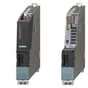
- CU310 DP Control Unit
- CompactFlash card for CU320-2
- CU320-2 DP Control Unit
Обзор
New system architecture with a central control module
In multi-axis drives, the individual drives are controlled from the higher-level control systems in such a way as to achieve the desired coordinated movement. This requires cyclic data exchange between the controller and the drives. In previous drive designs, this exchange took place via a field bus, requiring complex installation and configuration. SINAMICS takes a new approach in this respect: A central control module controls the drives for all connected axes and also establishes the technological links between the drives and/or axes. Since all the required data is stored in the central control module, it does not need to be transferred. Inter-axis connections can be established within a Control Unit and easily configured in the STARTER commissioning tool using a mouse.
- The SINAMICS control module can handle simple technological tasks by itself
- The CU320-2 DP or CU320-2 PN Control Units are used in conjunction with all Motor Modules or Line Modules for single or multi-motor drives. The CU310 DP or CU310 PN Control Units are used together with the Power Modules and single drives.
- Sophisticated motion control tasks can be implemented with the support of the more powerful, performance-graded Control Units D410, D425, D435 and D445 of SIMOTION D. Refer to Catalog PM 21 for information on SIMOTION.
Each of these Control Units is based on an object-oriented SINAMICS standard firmware, which contains all the most popular control modes and can be scaled to meet even the most advanced performance requirements.
The drive controls are supplied as ready-to-configure drive objects:
- Vector Control
- Speed-controlled drives with high speed and torque stability in general mechanical engineering systems
- Particularly suitable for induction motors
- Servo Control
- Drives with highly dynamic motion control
- Angular-locked synchronism with isochronous PROFIBUS/PROFINET
- For use in machine tools and clocked production machines
The most commonly used V/f control modes are stored in the "Vector control" drive object and are ideal for implementing even simple applications such as group drives with SIEMOSYN motors.
Overview of key open-loop and closed-loop control functions
| Closed-loop control types S120 | Open-loop control types S120 | Main functions S120 for booksize/chassis | Comment, note |
|---|---|---|---|---|
Vector control |
|
|
| Mixed operation with V/f control modes is possible; it is for this reason that the V/f control modes are stored only once in the "Vector control" drive object Position control can be selected as a function module from both Servo and Vector mode Permanent-magnet 1FW4 synchronous motors can be operated over the complete operating range in Vector control. |
Servo control |
|
|
| Mixed operation with V/f control modes is possible; it is for this reason that the V/f control modes are stored only once in the "Vector control" drive object Position control can be selected as a function module from both Servo and Vector mode. |
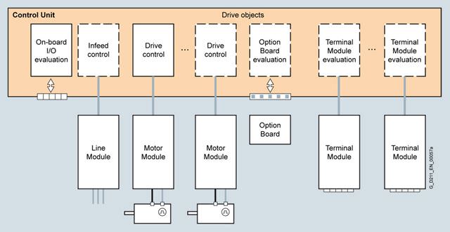
Drive objects
A drive object is a self-contained software function with its own parameters and, if necessary, its own fault messages and alarms.
Comprehensive package of open-loop and closed-loop control functions
A wide variety of standard functions such as setpoint input, data set changeover, controller optimization, kinetic buffering, etc. ensure a high degree of functional reliability and excellent flexibility when addressing the application.
BICO technology
Every drive object contains a large number of input and output variables which can be freely and independently interconnected using Binector Connector Technology (BICO). A binector is a logic signal which can assume the value 0 or 1. A connector is a numerical value, e.g. the actual speed or current setpoint.
Drive Control Chart (DCC)
Drive Control Chart (DCC) is an additional option for the easy configuration of technological functions for SINAMICS.
The block library encompasses a large selection of closed-loop, arithmetic and logic blocks, as well as a more comprehensive range of open-loop and closed-loop control functions. The user-friendly DCC Editor enables easy graphics-based configuration, allows control loop structures to be clearly represented and provides a high degree of reusability of diagrams that have already been created. DCC is an add-on to the STARTER commissioning tool.
CompactFlash Card
The functions of the drives are stored on a CompactFlash card. This card contains the firmware and parameter settings for all drives in the form of a project. The CompactFlash card can also hold additional projects, which means that the correct project can be accessed immediately when series machines of different types are commissioned. When the Control Unit has booted, the data on the CompactFlash card is read and loaded to the RAM.
The firmware is organized in objects. Drive objects are used to implement open-loop and closed-loop control functions for Line Modules, Motor Modules, Power Modules and other system components connected by DRIVE-CLiQ.
Integral safety functions (Safety Integrated)
The Control Units support an extensive range of safety functions.
The integrated safety functions are the Safety Integrated Basic functions
- STO = Safe Torque Off
- SBC = Safe Brake Control
- SS1 = Safe Stop 1 (Time controlled)
and the Safety Integrated Extended functions that require a license
- STO = Safe Torque Off
- SS1 = Safe Stop 1 (time and acceleration controlled)
- SS2 = Safe Stop 2
- SOS = Safe Operating Stop
- SLS = Safely Limited Speed
- SSM = Safe Speed Monitor
- SDI = Safe Direction
If the integrated safety functions are used, licenses, supplementary system components such as TM54F Terminal Modules, or suitable safety controls may be necessary.
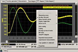
Diagnostics optimally supported by trace function
The time characteristics of input and output variables associated with drive objects can be measured by the integrated trace function and displayed using the STARTER commissioning tool. Several signals can be simultaneously traced. A recording can be triggered as a function of freely selectable boundary conditions, e.g. the value of an input or output variable.


 Ответ от производителя может занять до 5 дней и более.

