CU320-2 DP Control Unit Siemens

Обзор
The communication, open-loop and closed-loop control functions for one or more Line Modules and/or Motor Modules are executed in the CU320-2 DP Control Unit. It communicates with the higher-level control via PROFIBUS DP.
Дизайн
The CU320-2 DP Control Unit has the following interfaces as standard:
• 4 x DRIVE-CLiQ sockets for communication with other DRIVE-CLiQ nodes, e.g. Motor Modules, Active Line Modules, Sensor Modules, Terminal Modules
• 1 PROFIBUS interface with PROFIdrive profile
• 12 parameterizable digital inputs (isolated)
• 8 parameterizable bidirectional digital inputs/digital outputs (non-floating)
• 1 serial RS232 interface (e.g. to connect the AOP30 Advanced Operator Panel)
• 1 interface for the BOP20 Basic Operator Panel
• 1 slot for the CompactFlash card on which firmware and parameters are stored
• 1 slot for mounting an option module (e.g. TB30 Terminal Board)
• 2 rotary coding switches for manually setting the PROFIBUS address
• 1 Ethernet interface for commissioning and diagnostics
• 3 test sockets and one reference ground for commissioning support
• 1 connection for the electronics power supply via the 24 V DC supply connector
• 1 PE/protective conductor connection
• 1 ground connection
A shield connection for the signal cable shield on the option module is located on the CU320-2 DP Control Unit.
The available option slot is used to expand the interfaces, e.g. terminals or communication.
The status of the CU320-2 DP Control Unit is indicated via multicolor LEDs.
As the firmware and parameter settings are stored on a plug-in CompactFlash card, the Control Unit can be changed without the need for software tools.
The CU320-2 DP Control Unit can be mounted on the side of the Line Module via brackets integrated in a Line Module. The CU320-2 DP Control Unit can also be fixed to the wall of the control cabinet using the integrated fixing lugs.
Интеграция
DRIVE-CLiQ components such as Motor Modules and Active Line Modules can be connected to a CU320-2 DP Control Unit. The number of modules depends on the performance required, including duty type and additional functions.
The CU320-2 DP Control Unit and other connected components are commissioned and diagnosed using the STARTER commissioning tool from Version 4.1 SP5 and the installed SINAMICS Support Package SSP_SINAMICS_V4_3_2 or the AOP30 Advanced Operator Panel.
The BOP20 Basic Operator Panel can also be snapped onto the CU320-2 DP Control Unit during operation for troubleshooting.
The CU320-2 DP Control Unit requires a CompactFlash card with firmware version 4.3 or higher.
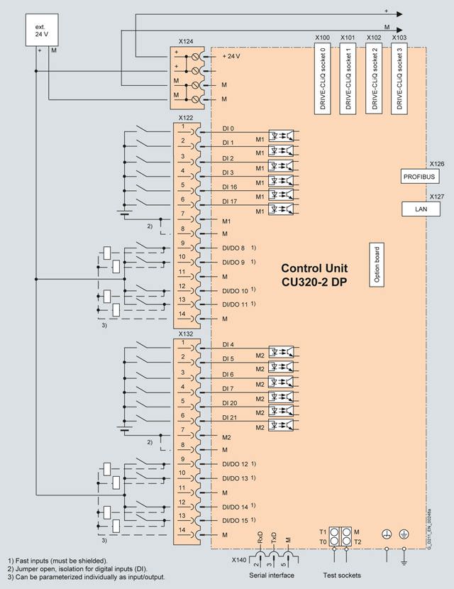
Connection example of a CU320-2 DP Control Unit
Технические данные
CU320-2 DP Control Unit 6SL3040-1MA00-0AA0 |
|
|---|---|
Current demand, max. At 24 V DC, | 1.0 A |
Conductor cross-section, max. | 2.5 mm2 |
Fuse protection, max. | 20 A |
Digital inputs | In accordance with IEC 61131-2 Type 1 12 isolated digital inputs 8 bidirectional non-isolated digital inputs/digital outputs |
| -3 … +30 V |
| -3 … +5 V |
| 15 … 30 V |
| 9 mA |
|
|
| 50 μs |
| 100 μs |
|
|
| 5 μs |
| 50 μs |
| 1.5 mm2 |
Digital outputs Continuously short-circuit proof | 8 bidirectional non-isolated digital inputs/digital outputs |
| 24 V DC |
| 500 mA |
|
|
| 150 μs / 400 μs |
| 75 μs / 100 μs |
| 1.5 mm2 |
Power loss | 24 W |
PE connection | M5 screw |
Ground connection | M5 screw |
Dimensions |
|
| 50 mm |
| 300 mm |
| 226 mm |
Weight, approx. | 2.3 kg |
Conformity | CE |
Approvals, according to | cULus |
1) The specified delay times refer to the hardware. The actual reaction time depends on the time slot in which the digital input or output is processed.


 Ответ от производителя может занять до 5 дней и более.

