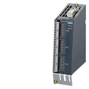
TM15 Terminal Module Siemens
Обзор
The number of available digital inputs and outputs within a drive system can be expanded with the TM15 Terminal Module.
Дизайн
The following are located on the TM15 Terminal Module:
- 24 bidirectional digital inputs/outputs (isolation in 3 groups with 8 channels each)
- 24 green status LEDs for indicating the logical signal status of the relevant terminal
- 2 DRIVE-CLiQ sockets
- 1 connection for the electronics power supply via the 24 V DC supply connector
- 1 PE/protective conductor connection
The TM15 Terminal Module can be snapped onto a TH 35 top-hat rail to EN 60715 (IEC 60715).
The signal cable shield can be connected to the TM15 Terminal Module via a shield connection terminal, e.g. Phoenix Contact type SK8 or Weidmüller type KLBÜ CO 1. The shield connection terminal must not be used for strain relief.
The status of the TM15 Terminal Module is indicated via a multicolor LED.
Интеграция
The TM15 Terminal Module communicates with the CU310 or CU320-2 Control Unit via DRIVE-CLiQ.
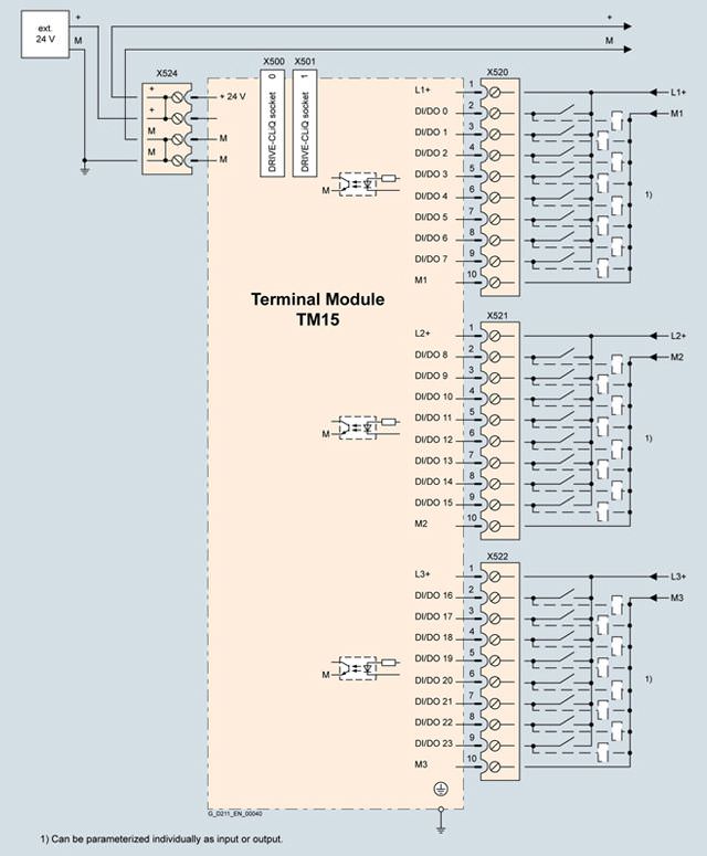
Example connection of a TM15 Terminal Module
Технические данные
TM15 Terminal Module 6SL3055-0AA00-3FA0 | |
|---|---|
Current demand, max. With 24 V DC without load | 0.15 A |
| 2.5 mm2 |
| 20 A |
Number of DRIVE-CLiQ sockets | 2 |
I/O devices | |
| Can be parameterized channel-by-channel as DI or DO |
| 24 |
| Yes, in groups of 8 |
| Plug-in screw-type terminals |
| 1.5 mm2 |
Digital inputs | |
| -3 … +30 V |
| -3 … +5 V |
| 15 … 30 V |
| 5 … 11 mA |
| |
| 50 μs |
| 100 μs |
Digital outputs Continuously short-circuit proof | |
| 24 V DC |
| 0.5 A |
|
|
| 50 μs |
| 100 μs |
| 150 μs |
| 225 μs |
|
|
| 2 A |
| 3 A |
| 4 A |
Power loss | < 3 W |
PE connection | M4 screw |
Dimensions |
|
| 50 mm |
| 150 mm |
| 111 mm |
Weight, approx. | 0.86 kg |
Conformity | CE |
Approvals, according to | cULus |
1) The specified delay times refer to the hardware. The actual reaction time depends on the time slot in which the digital input or output is processed.


 Ответ от производителя может занять до 5 дней и более.

