SITRANS P300 with PMC connection Siemens
Чертеж

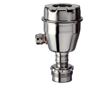
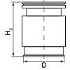
SITRANS P300 pressure transmitters for gage pressure, with PMC connection, dimensions in mm (inch)
The diagram shows a SITRANS P300 with an example of a flange. In this drawing the height is subdivided into H1 and H2.
H1 = Height of the SITRANS P300 up to a defined cross-section
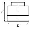
H2 = Height of the flange up to this defined cross-section
Only the height H2 is indicated in the dimensions of the flanges.
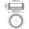 | 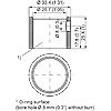 |
PMC Style Standard (left) and PMC Style Minibolt (right) weldable sockets, dimensions in mm (inch)
Material: Stainless steel, mat. no. 1.4404/316L
PMC Style standard | ||||
|---|---|---|---|---|
 | DN | PN | ∅D | H2 |
40.4 mm (1.6") | approx. 36.8 mm (1.4") | |||
PMC Style minibolt | ||||
|---|---|---|---|---|
 | DN | PN | ∅D | H2 |
26.3 mm (1.0") | approx. 33.1 mm (1.3") | |||
Технические данные
SITRANS P300 for gauge pressure with PMC connection for the paper industry | ||||
|---|---|---|---|---|
Input | ||||
Measured variable | Gauge pressure (flush-mounted) | |||
HART | PROFIBUS PA/ FOUNDATION Fieldbus | |||
Span (fully adjustable) or nominal measuring range and | Span | Nominal measuring range | Max. perm. operating pressure MAWP (PS) | Max. permissible test pressure |
0.01 ... 1 bar | 1 bar | 4 bar | 6 bar | |
0.04 ... 4 bar | 4 bar | 7 bar | 10 bar | |
0.16 ... 16 bar | 16 bar | 21 bar | 32 bar | |
Lower measuring limit | 100 mbar a/10 kPa a/1.45 psia | |||
Upper measuring limit | 100 % of max. span | |||
Output | HART | PROFIBUS PA/ FOUNDATION Fieldbus | ||
Output signal | 4 ... 20 mA | Digital PROFIBUS PA signal | ||
| 3.55 mA, factory preset to 3.84 mA | - | ||
| 23 mA, factory preset to 20.5 mA or optionally set to 22.0 mA | - | ||
Load | ||||
| RB ≤ (UH - 10.5 V)/0.023 A in Ω, | - | ||
| RB = 230 ... 500 Ω (SIMATIC PDM) or | - | ||
Physical bus | - | IEC 61158-2 | ||
Protection against polarity reversal | Protected against short-circuit and polarity reversal. Each connection against the other with max. supply voltage. | |||
Electrical damping (step width 0.1 s) | Set to 2 s (0 ... 100 s) | |||
Measuring accuracy | According to IEC 60770-1 | |||
Reference conditions |
| |||
Measuring span ratio r (spread, Turn-Down) | r = maximum measuring span/set measuring span or nominal measuring range | |||
Error in measurement at limit setting including hysteresis and reproducibility | ||||
| ||||
| ≤ 0.075 % | |||
| ≤ (0.005 · r + 0.05) % | |||
Influence of ambient temperature | ≤ (0.08 · r + 0.16) % | |||
Long-term stability (temperature change ±30 °C (±54 °F)) | ≤ (0.25 · r) % in 5 years | |||
Influence of mounting position | ≤ 0.1 mbar/0.01 kPa/0.00145 psi per 10° incline (zero point correction is possible with position error compensation) | |||
Effect of auxiliary power (in percent per voltage change) | 0.005 % per 1 V | |||
Measured-value resolution for PROFIBUS PA and FOUNDATION Fieldbus | 3 · 10-5 of nominal measuring range | |||
Rated conditions | ||||
Installation conditions | ||||
Ambient temperature | Observe the temperature class in areas subject to explosion hazard. | |||
| -40 ... +85 °C (-40 ... +185 °F) | |||
| -30 ... +85 °C (-22 ... +185 °F) | |||
| -50 ... +85 °C (-58 ... +185 °F) | |||
Climatic class | ||||
Condensation | Relative humidity 0 ... 100 % | |||
Degree of protection acc. to EN 60529 | IP65, IP68, NEMA 4X, enclosure cleaning, resistant to lyes, steam to 150 °C (302 °F) | |||
Electromagnetic Compatibility | ||||
| Acc. to EN 61326 and NAMUR NE 21 | |||
Process conditions | ||||
Temperature of medium | ||||
| -40 ... +100 °C (-40 ... +212 °F) | |||
Design | ||||
Weight (without options) | Approx. 1 kg (2.2 lb) | |||
Enclosure material | Stainless steel, mat. no. 1.4301/304 | |||
Material of parts in contact with the medium | ||||
| Hastelloy C276, mat. no. 2.4819 | |||
| Silicone oil | |||
Surface quality touched-by-media | Ra-values ≤ 0.8 µm (32 µ-inch)/welds Ra ≤ 1.6 µm (64 µ-inch) | |||
Power supply UH | HART | PROFIBUS PA/ FOUNDATION Fieldbus | ||
Terminal voltage on transmitter | 10.5 ... 42 V DC | - | ||
Auxiliary power | - | Bus-powered | ||
Separate power supply | - | Not necessary | ||
Bus voltage | ||||
| - | 9 ... 32 V | ||
| - | 9 ... 24 V | ||
Current consumption | ||||
| - | 12.5 mA | ||
| - | Yes | ||
| - | 15.5 mA | ||
Fault disconnection electronics (FDE) available | - | Yes | ||
Certificates and approvals | HART | PROFIBUS PA/ FOUNDATION Fieldbus | ||
Classification according to PED 97/23/EC | For gases of fluid group 1 and liquids of fluid group 1; complies with requirements of Article 3, paragraph 3 (sound engineering practice) | |||
Explosion protection | ||||
Intrinsic safety "i" | PTB 05 ATEX 2048 | |||
Marking | Ex II 1/2 G EEx ia/ib IIB/IIC T4, T5, T6 | |||
Permissible ambient temperature | ||||
| -40 ... +85 °C (-40 ... +185 °F) | |||
| -40 ... +70 °C (-40 ... +158 °F) | |||
| -40 ... +60 °C (-40 ... +140 °F) | |||
Connection | To certified intrinsically-safe circuits with peak values: Ui = 30 V, Ii = 100 mA, | To certified intrinsically-safe circuits with peak values: FISCO supply unit: Ui = 17.5 V, Ii = 380 mA, Linear barrier: Ui = 24 V, Ii = 250 mA, Pi = 1.2 W | ||
Effective internal capacitance | Ci = 6 nF | Ci = 1.1 nF | ||
Effective internal inductance | Li = 0.4 mH | Li ≤ 7 μH | ||
Explosion protection to FM for USA and Canada (cFMUS) | ||||
| Certificate of Compliance 3025099 CL I, DIV 1, GP ABCD T4 ... T6; CL II, DIV 1, GP EFG; CL III; CL I, ZN 0/1 AEx ia IIC T4 ... T6; CL I, DIV 2, GP ABCD T4 ... T6; CL II, DIV 2, GP FG; CL III | |||
| Certificate of Compliance 3025099C CL I, DIV 1, GP ABCD T4 ... T6; CL II, DIV 1, GP EFG; CL III; Ex ia IIC T4 ... T6; CL I, DIV 2, GP ABCD T4 ... T6; CL II, DIV 2, GP FG; CL III | |||
HART communication | |
|---|---|
HART | 230 ... 1100 Ω |
Protocol | HART Version 5.x |
Software for computer | SIMATIC PDM |
PROFIBUS PA communication | |
|---|---|
Simultaneous communication with master class 2 (max.) | 4 |
The address can be set using | Configuration tool Local operation (standard setting Address 126) |
Cyclic data usage | |
| One measured value: 5 byte Two measured values: 10 byte |
| Register operating mode: 1 byte Reset function due to metering: 1 byte |
Device profile | PROFIBUS PA Profile for Process Control Devices Version 3.0, Class B |
Function blocks | 2 |
| |
| Linearly rising or falling characteristic |
| 0 ... 100 s adjustable |
| Input /Output |
| One upper and lower warning limit and one alarm limit respectively |
| Can be reset and preset Optional direction of counting Simulation function of the register output |
| One upper and lower warning limit and one alarm limit respectively |
| 1 |
Transducer blocks | 2 |
| |
| Yes |
| Max. 31 nodes |
| Linear |
| Available |
| |
Simulation function | Available |
FOUNDATION Fieldbus communication | |
|---|---|
Function blocks | 3 function blocks analog input, 1 function block PID |
| |
| Yes, linearly rising or falling characteristic |
| 0 … 100 s |
| Output/input (can be locked within the device with a bridge) |
| parameterizable (last good value, substitute value, incorrect value) |
| Yes, one upper and lower warning limit and one alarm limit respectively |
| Yes |
| Standard FOUNDATION Fieldbus function block |
| 1 resource block |
Transducer blocks | 1 transducer block Pressure with calibration, 1 transducer block LCD |
| |
| Yes |
| Yes |
| Constant value or by means of parameterizable ramp function |


 Ответ от производителя может занять до 5 дней и более.

