SITRANS P310 for gauge pressure Siemens
Чертеж

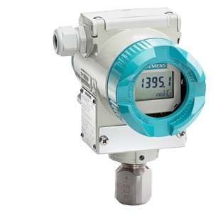
SITRANS P310 pressure transmitter for gauge pressure, dimensions in mm (inches)
Технические данные
SITRANS P310 for gauge pressure | ||||
|---|---|---|---|---|
Input | ||||
Measured variable | Gauge pressure | |||
Span (fully adjustable) or nominal measuring range, max. operating pressure (in accordance with 97/23/EC Pressure Equipment Directive) and max. test pressure (pursuant to DIN 16086) | Span | Max. perm. operating pressure MAWP (PS) | Max. permissible test pressure | |
0.01 ... 1 bar | 4 bar | 6 bar | ||
0.04 ... 4 bar | 7 bar | 10 bar | ||
0.16 ... 16 bar | 21 bar | 32 bar | ||
0.63 ... 63 bar | 67 bar | 100 bar | ||
1.6 ... 160 bar | 167 bar | 250 bar | ||
4 ... 400 bar | 400 bar | 600 bar | ||
7 ... 700 bar | 800 bar | 800 bar | ||
Low measuring limit | ||||
| 30 mbar a/3 kPa a/0.44 psia | |||
Upper measuring limit | 100% of maximum span | |||
Start of scale | Between the measuring limits (continuously adjustable) | |||
Output | ||||
Output signal | 4 ... 20 mA | |||
| 3.55 mA, factory preset to 3.84 mA | |||
| 23 mA, factory preset to 20.5 mA or optionally set to 22.0 mA | |||
Load | ||||
| RB ≤ (UH - 10.5 V)/0.023 A in Ω, | |||
| RB = 230 ... 500 Ω (SIMATIC PDM) or | |||
Protection against polarity reversal | Protected against short-circuit and polarity reversal. Each connection against the other with max. supply voltage. | |||
Electrical damping (step width 0.1 s) | Set to 2 s (0 ... 100 s) | |||
Measuring accuracy | According to IEC 60770-1 | |||
Reference conditions |
| |||
Measuring span ratio r (spread, Turn-Down) | r = maximum measuring span/set measuring span | |||
Error in measurement at limit setting including hysteresis and reproducibility | ||||
| ||||
| r ≤ 5 : | ≤ 0,065 % | ||
| r ≤ 3: | ≤ 0,075 % | ||
Influence of ambient temperature (in percent per 28 °C (50 °F)) | ||||
| ≤ (0.15 · r + 0.25) % | |||
Long-term stability (temperature change ±30 °C (±54 °F)) | ≤ (0.25 · r) % in 5 years | |||
Influence of mounting position | ≤ 0.05 mbar/0.005 kPa/0.000725 psi per 10° incline (zero point correction is possible with position error compensation) | |||
Effect of auxiliary power (in percent per voltage change) | 0.005 % per 1 V | |||
Rated conditions | ||||
Degree of protection according to IEC 60529 | IP66 (optional IP66/IP68), NEMA 4X | |||
Process temperature | ||||
| -40 ... +100 °C (-40 ... +212 °F) | |||
| -20 ... +60 °C (-4 ... +140 °F) | |||
Ambient conditions | ||||
| ||||
| -40 ... +85 °C (-40 ... +185 °F) | |||
| -30 ... +85 °C (-22 ... +185 °F) | |||
| -50 ... +85 °C (-58 ... +185 °F) | |||
| ||||
| Relative humidity 0 ... 100 % | |||
| ||||
| According to IEC 61326 and NAMUR NE 21 | |||
Design | ||||
Weight (without options) | Die-cast aluminum: ≈ 2.0 kg (≈ 4.4 lb) | |||
Enclosure material | Low-copper die-cast aluminum, GD-AlSi 12 or stainless steel precision casting, mat. no. 1.4408 | |||
Wetted parts materials | ||||
| Stainless steel, mat. no. 1.4404/316L or Hastelloy C4, mat. no. 2.4610 | |||
| Stainless steel, mat. no. 1.4404/316L or Hastelloy C276, mat. no. 2.4819 | |||
Measuring cell filling | Silicone oil or inert fill fluid (for oxygen measurement, maximum pressure 100 bar (1450 psi) at 60 °C (140 °F)) | |||
Process connection | G½B connection shank according to DIN EN 837-1; female thread ½-14 NPT or male thread M20x1.5 | |||
Material of mounting bracket | ||||
Steel | Sheet-steel, mat. no. 1.0330, chrome-plated | |||
Stainless steel | Sheet stainless steel, mat. no. 1.4301 (SS 304) | |||
Power supply UH | ||||
Terminal voltage on transmitter | 10.5 ... 45 V DC | |||
Certificates and approvals | HART | |||
Classification according to Pressure Equipment Directive (PED 97/23/EC) | For gases of fluid group 1 and liquids of fluid group 1; complies with requirements of article 3, paragraph 3 (sound engineering practice) | |||
Explosion protection | ||||
| PTB 13 ATEX 2007 X | |||
| Ex II 1/2 G Ex ia/ib IIC T4/T5/T6 Ga/Gb | |||
| -40 ... +85 °C (-40 ... +185 °F) temperature class T4; | |||
| To certified intrinsically-safe circuits with peak values: | |||
| Li = 0.4 mH, Ci = 6 nF | |||
| PTB 99 ATEX 1160 | |||
| Ex II 1/2 G Ex d IIC T4/T6 Gb | |||
| -40 ... +85 °C (-40 ... +185 °F) temperature class T4; | |||
| To circuits with operating values: UH = 10.5 ... 45 V DC | |||
| PTB 01 ATEX 2055 | |||
| Ex II 1 D Ex ta IIIC T120 °C Da | |||
| -40 ... +85 °C (-40 ... +185 °F) | |||
| 120 °C (248 °F) | |||
| To certified intrinsically-safe circuits with peak values: | |||
| Li = 0.4 mH, Ci = 6 nF | |||
| PTB 01 ATEX 2055 | |||
| Ex II 2 D Ex tb IIIC T120 °C Db | |||
| To circuits with operating values: UH = 10.5 ... 45 V DC; Pmax = 1.2 W | |||
| PTB 13 ATEX 2007 X | |||
| Ex II 2/3 G Ex nA IIC T4/T5/T6 Gc | |||
| Um = 45 V | |||
| To circuits with operating values: | |||
| Li = 0.4 mH, Ci = 6 nF | |||
| Certificate of Compliance 3008490 | |||
| CL I, DIV 1, GP ABCD T4...T6; CL II, DIV 1, GP EFG; CL III; CL I, ZN 0/1 AEx ia IIC T4...T6; CL I, DIV 2, GP ABCD T4...T6; CL II, DIV 2, GP FG; CL III | |||
| Certificate of Compliance 1153651 | |||
| CL I, DIV 1, GP ABCD T4...T6; CL II, DIV 1, GP EFG; CL III; Ex ia IIC T4...T6; CL I, DIV 2, GP ABCD T4...T6; CL II, DIV 2, GP FG; CL III | |||
Communication | ||||
HART | 230 ... 1100 Ω | |||
Protocol | HART Version 5.x | |||
Software for computer | SIMATIC PDM | |||


 Ответ от производителя может занять до 5 дней и более.

