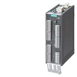
TM31 Terminal Module Siemens
Обзор
The TM31 Terminal Module can be used to increase the number of available digital inputs and outputs and the number of analog inputs and outputs within a drive system.
The TM31 Terminal Module also features relay outputs with changeover contact and a temperature sensor input.
Дизайн
The following are located on the TM31 Terminal Module:
- 8 digital inputs
- 4 bidirectional digital inputs/outputs
- 2 relay outputs with changeover contact
- 2 analog inputs
- 2 analog outputs
- 1 temperature sensor input (KTY84-130 or PTC)
- 2 DRIVE-CLiQ sockets
- 1 connection for the electronics power supply via the 24 V DC supply connector
- 1 PE/protective conductor connection
The TM31 Terminal Module can be snapped onto a TH 35 top-hat rail to EN 60715 (IEC 60715).
The signal cable shield can be connected to the TM31 Terminal Module via a shield connection terminal, e.g. Phoenix Contact type SK8 or Weidmüller type KLBÜ CO 1. The shield connection terminal must not be used for strain relief.
The status of the TM31 Terminal Module is indicated via a multicolor LED.
Интеграция
The TM31 Terminal Module communicates with the CU310 or CU320-2 Control Unit via DRIVE-CLiQ.
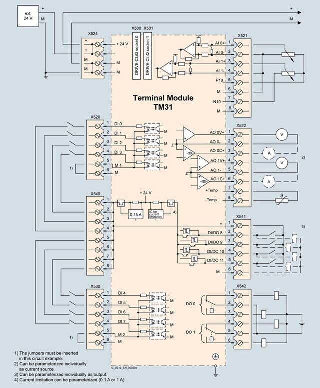
Example connection of a TM31 Terminal Module
Технические данные
TM31 Terminal Module 6SL3055-0AA00-3AA1 | |
|---|---|
Current demand, max. At 24 V DC without taking into account the digital outputs and the DRIVE-CliQ supply | 0.2 A |
| 2.5 mm2 |
| 20 A |
Digital inputs In accordance with IEC 61131-2 Type 1 | |
| -3 … +30 V |
| -3 … +5 V |
| 15 … 30 V |
| 10 mA |
| |
| 50 μs |
| 100 μs |
| 1.5 mm2 |
Digital outputs Continuously short-circuit proof | |
| 24 V DC |
| 100 mA |
| 400 mA |
| |
| 150 μs at 0.5 A resistive load |
| 500 μs |
| 1.5 mm2 |
Analog inputs A switch is used to toggle between voltage and current input | |
| |
| -10 … +10 V |
| 100 kΩ |
| |
| 4 … 20 mA, -20 … +20 mA, 0 … 20 mA |
| 250 Ω |
| 11 bit + sign |
| 1.5 mm2 |
Analog outputs Continuously short-circuit proof | |
| -10 … +10 V |
| -3 … +3 mA |
| 4 … 20 mA, -20 … +20 mA, 0 … 20 mA |
| 500 Ω for outputs in the range -20 … +20 mA |
| 11 bit + sign |
| 1.5 mm2 |
Relay outputs Changeover contacts | |
| 8 A |
| 250 V AC, 30 V DC |
|
|
| 2000 VA (cos φ = 1) |
| 240 W (resistive load) |
| 100 mA |
| 2.5 mm2 |
Power loss | < 5 W |
PE connection | M4 screw |
Dimensions |
|
| 50 mm |
| 150 mm |
| 111 mm |
Weight, approx. | 0.87 kg |
Conformity | CE |
Approvals, according to | cULus |
1) The specified delay times refer to the hardware. The actual reaction time depends on the time slot in which the digital input or output is processed.
2) f the analog input is to be operated in the signal processing sense with continuously variable input voltage, the sampling frequency fa = 1/ttime slice must be at least twice the value of the highest signal frequency fmax.


 Ответ от производителя может занять до 5 дней и более.

