SITRANS P410, Technical description Siemens
Область применения
SITRANS P410 pressure transmitters can be used in industrial areas with extreme chemical and mechanical loads. Electromagnetic compatibility in the range 10 kHz to 1 GHz makes the P410 suitable for locations with high electromagnetic emissions.
Pressure transmitters with type of protection "Flameproof enclosure" may be installed in hazardous areas (zone 1) or in zone 0. The pressure transmitters are provided with an EC type examination certificate and comply with the corresponding harmonized European standards (ATEX).
Pressure transmitters with the type of protection "Intrinsic safety" for use in zone 0 may be operated with power supply units of category "ia" and "ib".
The transmitters can be equipped with various designs of remote seals for special applications such as the measurement of highly viscous substances.
The pressure transmitter can be operated locally over 3 input buttons or programmed externally over HART or over PROFIBUS PA or FOUNDATION Fieldbus interface.
Pressure transmitters for gauge pressure
Measured variable: Gauge pressure of aggressive and non-aggressive gases, vapors and liquids.
Span (fully adjustable)
for P410 with HART: 0.01 bar to 160 bar (0.15 psi to 2321 psi)
Nominal measuring range
for P410 with PROFIBUS PA and FOUNDATION Fieldbus: 1 bar to 160 bar (14.5 psi to 2321 psi)
Pressure transmitters for differential pressure and flow
Measured variables:
- Differential pressure
- Small positive or negative overpressure
- Flow q ~ √Δp (together with a primary differential pressure device (see section "Flowmeters"))
Span (fully adjustable)
for P410 with HART: 1 mbar to 30 bar (0.0145 to 435 psi)
Nominal measuring range
for P410 with PROFIBUS PA and FOUNDATION Fieldbus: 20 mbar to 30 bar (0.29 to 435 psi)
Обзор
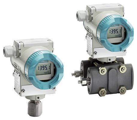
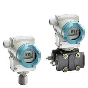
SITRANS P410 pressure transmitters are digital pressure transmitters with a high level of operating convenience. Technically, they are based on the SITRANS P DS III but offer an increased measuring accuracy of 0.04 %. This means the SITRANS P410 is perfectly suited for measuring tasks with increased accuracy requirements. The parameterization is performed using input buttons or via HART or via PROFIBUS PA or FOUNDATION Fieldbus interface.
The comprehensive functionality makes for precise adjustment of the pressure transmitter to the requirements of the plant. Operation is very simple, despite the variety of setting options.
Pressure transmitters with type of protection "Intrinsic safety" and "Explosion-proof" may be installed in hazardous areas (zone 1) or in zone 0. The transmitters are provided with an EC type examination certificate and comply with the respective harmonized European standards (ATEX).
The transmitters can be equipped with various designs of remote seals for special applications such as the measurement of highly viscous substances.
SITRANS P410 pressure transmitters are available in various versions for measuring:
- Gauge pressure
- Differential pressure
- Volume flow
- Mass flow
Дизайн
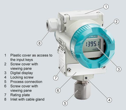
Front view
The transmitter consists of various components depending on the order. The possible versions are listed in the ordering information. The components described below are the same for all transmitters.
The rating plate (7, Figure "Front view") with the Order No. is located on the side of the housing. The specified number together with the ordering information provide details on the optional design details and on the possible measuring range (physical properties of built-in sensor element).
The approval label is located on the opposite side.
The housing is made of die-cast aluminum or stainless steel precision casting. A round cover is screwed on at the front and rear of the housing. The front cover (2) can be fitted with a viewing pane so that the measured values can be read directly on the display. The inlet (8) for the electrical connection is located either on the left or right side. The unused opening on the opposite side is sealed by a blanking plug. The protective earth connection is located on the rear of the housing.
The electrical connections for the power supply and screen are accessible by unscrewing the rear cover. The bottom part of the housing contains the measuring cell with process connection (5). The measuring cell is prevented from rotating by a locking screw (4). As the result of this modular design, the measuring cell and the electronics can be replaced separately from each other. The set parameter data are retained.
At the top of the housing is a plastic cover (1), which hides the input keys.
Example of screwed-on measuring point label

Функции
Operation of electronics with HART communication

Function diagram of electronics
The bridge output voltage created by the sensor (1, Figure "Function diagram of electronics") is amplified by the measuring amplifier (2) and digitized in the analog-to-digital converter (3). The digital information is evaluated in a microcontroller, corrected for linearity and temperature response, and converted in a digital-to-analog converter (5) into an output current of 4 to 20 mA.
The diode circuit (10) protects against incorrect polarity.
The data specific to the measuring cell, the electronics data, and the parameter data are stored in the two non-volatile memories (6). One memory is coupled to the measuring cell, the other to the electronics. As the result of this modular design, the electronics and the measuring cell can be replaced separately from each other.
Using the 3 input buttons (8) you can parameterize the pressure transmitter directly at the measuring point. The input buttons can also be used to control the view of the measurement results, the error messages and the operating modes on the display (9).
The HART modem (7) permits parameterization using a protocol according to the HART specification.
The pressure transmitters with spans ≤ 63 bar measure the input pressure compared to atmosphere, transmitters with spans ≥ 160 bar compared to vacuum.
Operation of electronics with PROFIBUS PA communication
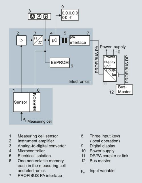
Function diagram of electronics
The bridge output voltage created by the sensor (1, Figure "Function diagram of electronics") is amplified by the measuring amplifier (2) and digitized in the analog-to-digital converter (3). The digital information is evaluated in the microcontroller, correct for linearity and temperature response, and made available on the PROFIBUS PA via an electrically isolated PA interface (7).
The data specific to the measuring cell, the electronics data, and the parameter data are stored in the two non-volatile memories (6). One memory is coupled to the measuring cell, the other to the electronics. As the result of this modular design, the electronics and the measuring cell can be replaced separately from each other.
Using the three input buttons (8) you can parameterize the pressure transmitter directly at the measuring point. The input buttons can also be used to control the view of the measurement results, the error messages and the operating modes on the display (9).
The results with status values and diagnostic values are transferred by cyclic data transmission on the PROFIBUS PA. Parameterization data and error messages are transferred by acyclic data transmission. Special software such as SIMATIC PDM is required for this.
Operation of electronics with FOUNDATION Fieldbus communication

Function diagram of electronics
The bridge output voltage created by the sensor (1, Figure "Function diagram of electronics") is amplified by the measuring amplifier (2) and digitized in the analog-to-digital converter (3). The digital information is evaluated in the microcontroller, corrected for linearity and temperature response and made available on the FOUNDATION Fieldbus via an electrically isolated FOUNDATION Fieldbus interface (7).
The data specific to the measuring cell, the electronics data, and the parameter data are stored in the two non-volatile memories (6). One memory is coupled to the measuring cell, the other to the electronics. As the result of this modular design, the electronics and the measuring cell can be replaced separately from each other.
Using the three input buttons (8) you can parameterize the pressure transmitter directly at the measuring point. The input buttons can also be used to control the view of the measurement results, the error messages and the operating modes on the display (9).
The results with status values and diagnostic values are transferred by cyclic data transmission on the FOUNDATION Fieldbus. Parameterization data and error messages are transferred by acyclic data transmission. Special software such as National Instruments Configurator is required for this.
Mode of operation of the measuring cells
Measuring cell for gauge pressure
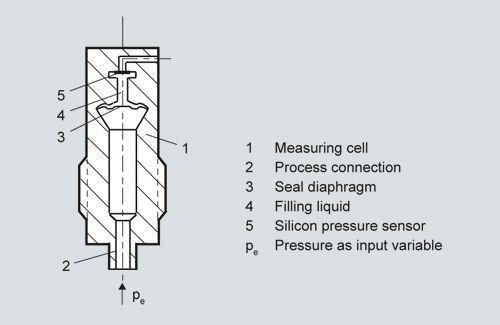
Measuring cell for gauge pressure, function diagram
The pressure pe is applied through the process connection (2, "Measuring cell for gauge pressure, function diagram") to the measuring cell (1). This pressure is subsequently transmitted further through the seal diaphragm (3) and the fill fluid (4) to the silicon pressure sensor (5) whose measuring diaphragm is then flexed. This changes the resistance of the four piezo-resistors fitted in the diaphragm in a bridge circuit. This change in resistance results in a bridge output voltage proportional to the absolute pressure.
Measuring cell for differential pressure and flow rate
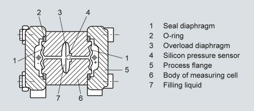
Measuring cell for differential pressure and flow, function diagram
The differential pressure is transmitted through the seal diaphragms (1, Figure "Measuring cell for differential pressure and flow, function diagram") and the fill fluid (7) to the silicon pressure sensor (4).
The measuring diaphragm is flexed by the applied differential pressure. This changes the resistance of the four piezo-resistors fitted in the diaphragm in a bridge circuit. This change in resistance results in a bridge output voltage proportional to the differential pressure.
An overload diaphragm is installed to provide protection from overloads. If the measuring limits are exceeded, the overload diaphragm (3) is flexed until the seal diaphragm rests on the body of the measuring cell (6), thus protecting the silicon pressure sensor from overloads.
Parameterization of P410
Depending on the version, there are a range of options for parameterizing the pressure transmitter and for setting or scanning the parameters.
Parameterization using the input buttons (local operation)
With the input buttons you can easily set the most important parameters without any additional equipment.
Parameterization using HART
Parameterization using HART is performed with a HART Communicator or a PC.

Communication between a HART Communicator and a pressure transmitter
When parameterizing with the HART Communicator, the connection is made directly to the 2-wire cable.
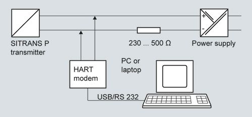
HART communication between a PC communicator and a pressure transmitter
When parameterizing with a PC, the connection is made through a HART modem.
The signals needed for communication in conformity with the HART 5.x or 6.x protocols are superimposed on the output current using FSK (Frequency Shift Keying).
Adjustable P410 parameters with HART
Parameter | Input buttons (DS III with HART) | HART communication |
|---|---|---|
Start of scale | x | x |
Full scale value | x | x |
Electrical damping | x | x |
Blind adjustment of the start of scale value | x | x |
Blind adjustment of the full scale value | x | x |
Zero-point adjustment | x | x |
Current simulator | x | x |
Fault current | x | x |
Keyboard lock and write protection | x | x 1) |
Type of unit, unit | x | x |
Characteristic (linear / square-rooted) | x 2) | x 2) |
Input of characteristic | x | |
Freely-programmable LCD | x | |
Diagnostic functions | x |
1) Cancel apart from write protection
2) Only differential pressure
Diagnostic functions for P410 with HART
- Zero correction display
- Event counter
- Limiter
- Saturation alarm
- Min/max pointer
- Simulation functions
- Maintenance timer
Available physical units of display for DS III with HART
Physical variable | Physical units |
Pressure (setting can also be made in the factory) | Pa, MPa, kPa, bar, mbar, torr, atm, psi, g/cm2, kg/cm2, inH2O, inH2O (4 °C), mmH2O, ftH2O (20 °C), inHg, mmHg |
Level (height data) | m, cm, mm, ft, in |
Volume | m3, dm3, hl, yd3, ft3, in3, US gallon, lmp. gallon, bushel, barrel, barrel liquid |
Weight | g, kg, t, lb, Ston, Lton, oz |
Volume flow | m3/d, m3/h, m3/s, l/min, l/s, ft3/d, ft3/min, ft3/s, US gallon/min, US gallon/s |
Mass flow | t/d, t/h, t/min, kg/d, kg/h, kg/min, kg/s, g/d, g/h, g/min, g/s, lb/d, lb/h, lb/min, lb/s, LTon/d, LTon/h, STon/d, STon/h, STon/min |
Temperature | K, °C, °F, °R |
Other | %, mA |
Parameterization through PROFIBUS PA interface
Fully digital communication through PROFIBUS PA, profile 3.0, is particularly user-friendly. Via PROFIBUS, the P410 with PROFIBUS PA is connected to a process control system such as SIMATIC PSC 7. Communication is possible even in a hazardous area.
For parameter assignment via PROFIBUS, you need suitable software, e.g. SIMATIC PDM (Process Device Manager)
Parameterization through FOUNDATION Fieldbus interface
Fully digital communication through FOUNDATION Fieldbus is particularly user-friendly. Through the FOUNDATION Fieldbus the P410 with FOUNDATION Fieldbus is connected to a process control system. Communication is possible even in a hazardous area.
For parameterization through the FOUNDATION Fieldbus you need suitable software, e. g. National Instruments Configurator.
Adjustable parameters for P410 with PROFIBUS PA and FOUNDATION Fieldbus
Adjustable parameters | Input buttons | PROFIBUS PA and FOUNDATION Fieldbus interface |
|---|---|---|
Electrical damping | x | x |
Zero-point adjustment (correction of position) | x | x |
Buttons and/or function disabling | x | x |
Source of measured-value display | x | x |
Physical units available for the display | x | x |
Position of decimal point | x | x |
Bus address | x | x |
Adjustment of characteristic | x | x |
Input of characteristic | x | |
Freely-programmable LCD | x | |
Diagnostic functions | x |
Diagnostic functions for P410 with PROFIBUS PA and FOUNDATION Fieldbus
- Event counter
- Min/max pointer
- Maintenance timer
- Simulation functions
- Display of zero-point correction
- Limiter
- Saturation alarm
Physical units available for the display
Physical variable | Physical units |
Pressure (setting can also be made in the factory) | MPa, kPa, Pa, bar, mbar, torr, atm, psi, g/cm2, kg/cm2, mmH2O, mmH2O (4 °C), inH2O, inH2O (4 °C), ftH2O (20 °C), mmHg, inHg |
Level (height data) | m, cm, mm, ft, in, yd |
Volume | m3, dm3, hl, yd3, ft3, in3, US gallon, lmp. gallon, bushel, barrel, barrel liquid |
Volume flow | m3/s, m3/min, m3/h, m3/d, l/s, l/min, l/h, l/ d, Ml/d, ft3/s, ft3/min, ft3/h, ft3/d, US gallon/s, US gallon/min, US gallon/h, US gallon/d, bbl/s, bbl/min, bbl/h, bbl/d |
Mass flow | g/s, g/min, g/h, g/d, kg/s, kg/min, kg/h, kg/d, t/s, t/min, t/h, /t/d, lb/s, lb/min, lb/h, lb/d, STon/s, STon/min, STon/h, STon/d, LTon/s, LTon/min, LTon/h, LTon/d |
Total mass flow | t, kg, g, lb, oz, LTon, STon |
Temperature | K, °C, °F, °R |
Other | % |
Особенности
- High quality and service life
- For aggressive and non-aggressive gases, vapors and liquids
- Extensive diagnostics and simulation functions
- Minimal conformity error
- Good long-term stability
- Wetted parts made of high-grade materials (e.g., stainless steel, Hastelloy)
- Infinitely adjustable spans from 0.01 bar to 160 bar (0.15 psi to 2321 psi) for P410 with HART interface
- Nominal measuring ranges from 1 bar to 160 bar (14.5 psi to 2321 psi) for P410 with PROFIBUS PA and FOUNDATION Fieldbus interface
- High measuring accuracy
- Parameterization over input buttons and HART, PROFIBUS PA or FOUNDATION Fieldbus interface.


 Ответ от производителя может занять до 5 дней и более.

