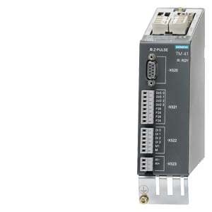
TM41 Terminal Module Siemens
Обзор
The TM41 Terminal Module supplies TTL signals which emulate an incremental encoder, e.g. to a higher-level control. The encoder interface (incremental encoder emulation) can be linked to an encoder signal from the Control Unit, e.g. incremental encoder sin/cos, by parameter assignment.
The TM41 Terminal Module increases the number of digital inputs/outputs and analog inputs that are available in the drive system.
Дизайн
The following are located on the TM41 Terminal Module:
- 4 bidirectional digital inputs/outputs
- 4 digital inputs (with electrical isolation)
- 1 analog input
- 1 interface for emulation of TTL incremental encoder (RS422)
- 1 LED for signaling zero mark detection for encoder interface
- 2 DRIVE-CLiQ sockets
- 1 connection for the 24 V DC supply of the digital outputs
- 1 connection for the electronics power supply via the 24 V DC supply connector
- 1 PE/protective conductor connection
The TM41 Terminal Module can be snapped onto a TH 35 top-hat rail to EN 60715 (IEC 60715).
The signal cable shield can be connected to the TM41 Terminal Module via a shield connection terminal, e.g. Phoenix Contact type SK8 or Weidmüller type KLBÜ CO 1. The shield connection terminal must not be used for strain relief.
The status of the TM41 Terminal Module is indicated via a multicolor LED.
An LED next to the interface for TTL pulse encoder emulation is illuminated as soon as a zero mark is detected.
Интеграция
The TM41 Terminal Module communicates with the CU310 or CU320-2 Control Unit via DRIVE-CLiQ.
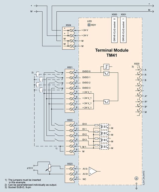
Example of connection of a TM41 Terminal Module
Технические данные
TM41 Terminal Module 6SL3055-0AA00-3PA1 |
|
|---|---|
Current demand (X524 at 24 V DC) without DRIVE-CliQ supply or digital outputs (X514) | 0.2 A |
| 2.5 mm2 |
| 20 A |
I/O devices |
|
| Individually parameterizable as DI or DO |
| 4 |
| 4 |
| Plug-in screw-type terminals |
| 1.5 mm2 |
Digital inputs |
|
| |
| -3 … +30 V |
| -30 … +30 V |
| |
| -3 … +5 V |
| -30 … +5 V |
| 15 … 30 V |
| < 9 mA |
|
|
| 3 ms |
| 3 ms |
Digital outputs Continuously short-circuit proof |
|
| 24 V DC |
| 0.5 A |
|
|
| 50 μs |
| 100 μs |
| 75 μs |
| 150 μs |
Analog input Difference |
|
| -10 … +10 V |
| ≥ 40 kΩ |
| 13 bit + sign |
Pulse encoder emulation |
|
| TTL (RS422), A+, A-, B+, B-, zero track N+, N- |
| 512 kHz |
| 1 : 1 for incremental encoder sin/cos and TTL/HTL |
PE connection | M4 screw |
Dimensions |
|
| 50 mm |
| 150 mm |
| 111 mm |
Weight, approx. | 0.85 kg |
Conformity | CE |
Approvals, according to | cULus |
1) The specified delay times refer to the hardware. The actual reaction time depends on the time slot in which the digital input or output is processed.
2) f the analog input is to be operated in the signal processing sense with continuously variable input voltage, the sampling frequency fa = 1/ttime slice must be at least twice the value of the highest signal frequency fmax.


 Ответ от производителя может занять до 5 дней и более.

