SITRANS P410 for differential pressure and flow Siemens
Чертеж
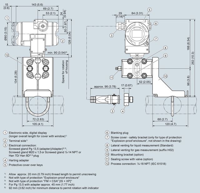
SITRANS P410 pressure transmitter for differential pressure and flow rate, dimensions in mm (inch)
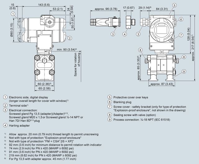
SITRANS P410 pressure transmitter for differential pressure and flow with process covers for vertical differential pressure lines, option "H03", dimensions in mm (inch)
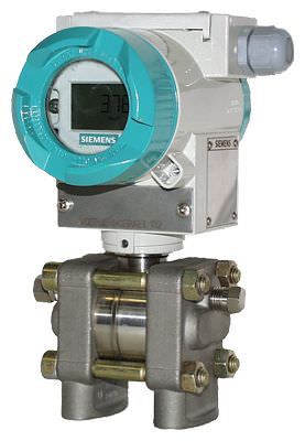
SITRANS P410 pressure transmitter for differential pressure and flow rate with caps for vertical differential pressure lines
Технические данные
SITRANS P, DS III for differential pressure and flow | |||
|---|---|---|---|
Input | |||
Measured variable | Differential pressure and flow | ||
Span (fully adjustable) or measuring range and maximum operating pressure (pursuant to 97/23/EC Pressure Equipment Directive) | HART | PROFIBUS PA and FOUNDATION Fieldbus | |
Span | Nominal measuring range | Max. perm. operating pressure MAWP (PS) | |
2.5 ... 250 mbar | 2.5 ... 250 mbar | 160 bar | |
6 ... 600 mbar | 6 ... 600 mbar | ||
16 ... 1600 mbar | 16 ... 1600 mbar | ||
50 ... 5000 mbar | 50 ... 5000 mbar | ||
0.3 ... 30 bar | 0.3 ... 30 bar | ||
6 ... 600 mbar | 6 ... 600 mbar | 420 bar | |
16 ... 1600 mbar | 16 ... 1600 mbar | ||
50 ... 5000 mbar | 50 ... 5000 mbar | ||
0.3 ... 30 bar | 0.3 ... 30 bar | ||
Low measuring limit | |||
| -100% of max. measuring range (-33 % for measuring cell 30 bar/3 MPa/435 psi) or 30 mbar a/3 kPa a/0.44 psi a | ||
Upper measuring limit | 100% of maximum span | ||
Start of scale | Between the measuring limits (continuously adjustable) | ||
Output | HART | PROFIBUS PA and FOUNDATION Fieldbus | |
Output signal | 4 ... 20 mA | Digital PROFIBUS PA and FOUNDATION Fieldbus signal | |
| 3.55 mA, factory preset to 3.84 mA | - | |
| 23 mA, factory preset to 20.5 mA or optionally set to 22.0 mA | - | |
Load | |||
| RB ≤ (UH - 10.5 V)/0.023 A in Ω, | - | |
| RB = 230 ... 500 Ω (SIMATIC PDM) or | - | |
Physical bus | - | IEC 61158-2 | |
Protection against polarity reversal | Protected against short-circuit and polarity reversal. Each connection against the other with max. supply voltage. | ||
Electrical damping (step width 0.1 s) | Set to 2 s (0 ... 100 s) | ||
Measuring accuracy | According to IEC 60770-1 | ||
Reference conditions |
| ||
Measuring span ratio r (spread, Turn-Down) | r = maximum measuring span/set measuring span or nominal measuring range | ||
Error in measurement at limit setting including hysteresis and reproducibility | |||
| |||
| r ≤ 5 : | ≤ 0.04 % | |
| |||
| r ≤ 5 : | ≤ 0.04 % | |
| |||
| r ≤ 5 : | ≤ 0.08 % | |
Influence of ambient temperature (in percent per 28 °C (50 °F)) | |||
| ≤ (0.025 · r + 0.125) % | ||
Effect of static pressure | |||
| ≤ (0.1 · r) % per 70 bar | ||
| ≤ (0.2 · r) % per 70 bar | ||
| |||
| ≤ 0.14% per 70 bar | ||
Long-term stability (temperature change ±30 °C (±54 °F)) | Static pressure max. 70 bar/7 MPa/1015 psi | ||
| ≤ (0.125 · r) % in 5 years | ||
| ≤ (0.25 · r) % in 5 years | ||
Effect of mounting position (in pressure per change of angle) | ≤ 0.7 mbar/0.07 kPa/0.028 inH2O per 10° incline (zero point correction is possible with position error compensation) | ||
Effect of auxiliary power (in percent per voltage change) | 0.005 % per 1 V | ||
Measured-value resolution for PROFIBUS PA and FOUNDATION Fieldbus | 3 · 10-5 of nominal measuring range | ||
Rated conditions | |||
Degree of protection acc. to IEC 60529 | IP66 (optional IP66/IP68), NEMA 4X | ||
Process temperature | |||
| -40 ... +100 °C (-40 ... +212 °F); -20 ... +100 °C (-4 ... +212 °F) with 30 bar measuring cell | ||
| -20 ... +100 °C (-4 ... +212 °F) | ||
| -20 ... +60 °C (-4 ... +140 °F) | ||
Ambient conditions | |||
| |||
| -40 ... +85 °C (-40 ... +185 °F) | ||
| -30 ... +85 °C (-22 ... +185 °F) | ||
| -50 ... +85 °C (-58 ... +185 °F) | ||
| |||
| Relative humidity 0 ... 100 % | ||
| |||
| According to IEC 61326 and NAMUR NE 21 | ||
Design | |||
Weight (without options) | Die-cast aluminum: ≈ 4.5 kg (≈ 9.9 lb) | ||
Enclosure material | Low-copper die-cast aluminum, GD-AlSi 12 or stainless steel precision casting, mat. no. 1.4408 | ||
Wetted parts materials | |||
| Stainless steel, mat. no. 1.4404/316L or Hastelloy C276, mat. no. 2.4819 | ||
| Stainless steel, mat. no. 1.4408, Hastelloy C4, mat. no. 2.4610 | ||
| FPM (Viton) or optionally: PTFE, FEP, FEPM and NBR | ||
Measuring cell filling | Silicone oil or inert fill fluid (for oxygen measurement, maximum pressure 100 bar (1450 psi) at 60 °C (140 °F)) | ||
Process connection | Female thread ¼-18 NPT and flange connection with mounting thread M10 to DIN 19213 or 7/16-20 UNF to IEC 61518 | ||
Material of mounting bracket | |||
| Sheet-steel, mat. no. 1.0330, chrome-plated | ||
| Sheet stainless steel, mat. no. 1.4301 (SS 304) | ||
Power supply UH | HART | PROFIBUS PA/FOUNDATION Fieldbus | |
Terminal voltage on transmitter | 10.5 ... 45 V DC | - | |
Auxiliary power | Bus-powered | ||
Separate supply voltage | - | Not necessary | |
Bus voltage | |||
| - | 9 ... 32 V | |
| - | 9 ... 24 V | |
Current consumption | |||
| - | 12.5 mA | |
| - | Yes | |
| - | 15.5 mA | |
Fault disconnection electronics (FDE) available | - | Yes | |
Certificates and approvals | HART | PROFIBUS PA/FOUNDATION Fieldbus | |
Classification according to Pressure Equipment Directive (PED 97/23/EC) | |||
PN 32/160 (MAWP 464/2320 psi) | For gases of fluid group 1 and liquids of fluid group 1; complies with requirements of article 3, paragraph 3 (sound engineering practice) | ||
PN 420 (MAWP 6092 psi) | For gases of fluid group 1 and liquids of fluid group 1; complies with basic safety requirements of Article 3, paragraph 1 (appendix 1); assigned to category III, conformity evaluation module H by the TÜV Nord. | ||
Explosion protection | |||
| PTB 13 ATEX 2007 X | ||
| Ex II 1/2 G Ex ia/ib IIC T4/T5/T6 Ga/Gb | ||
| -40 ... +85 °C (-40 ... +185 °F) temperature class T4; | ||
| To certified intrinsically-safe circuits with peak values: | FISCO supply unit: Linear barrier: | |
| Li = 0.4 mH, Ci = 6 nF | Li = 7 μH, Ci = 1.1 nF | |
| PTB 99 ATEX 1160 | ||
| Ex II 1/2 G Ex d IIC T4/T6 Gb | ||
| -40 ... +85 °C (-40 ... +185 °F) temperature class T4; | ||
| To circuits with operating values: UH = 10.5 ... 45 V DC | To circuits with operating values: UH = 9 ... 32 V DC | |
| PTB 01 ATEX 2055 | ||
| Ex II 1 D Ex ta IIIC T120°C Da | ||
| -40 ... +85 °C (-40 ... +185 °F) | ||
| 120 °C (248 °F) | ||
| To certified intrinsically-safe circuits with peak values: | FISCO supply unit: Linear barrier: | |
| Li = 0.4 mH, Ci = 6 nF | Li = 7 μH, Ci = 1.1 nF | |
| PTB 01 ATEX 2055 | ||
| Ex II 2 D Ex tb IIIC T120°C Db | ||
| To circuits with operating values: UH = 10.5 ... 45 V DC; Pmax = 1.2 W | To circuits with operating values: UH = 9 ... 32 V DC; Pmax = 1 W | |
| PTB 13 ATEX 2007 X | ||
| Ex II 2/3 G Ex nA IIC T4/T5/T6 Gc | ||
| Um = 45 V | Um = 32 V | |
| To circuits with operating values: | FISCO supply unit: Linear barrier: | |
| Li = 0.4 mH, Ci = 6 nF | Li = 7 μH, Ci = 1.1 nF | |
| Certificate of Compliance 3008490 | ||
| CL I, DIV 1, GP ABCD T4...T6; CL II, DIV 1, GP EFG; CL III; CL I, ZN 0/1 AEx ia IIC T4...T6; CL I, DIV 2, GP ABCD T4...T6; CL II, DIV 2, GP FG; CL III | ||
| Certificate of Compliance 1153651 | ||
| CL I, DIV 1, GP ABCD T4...T6; CL II, DIV 1, GP EFG; CL III; Ex ia IIC T4...T6; CL I, DIV 2, GP ABCD T4...T6; CL II, DIV 2, GP FG; CL III | ||
HART communication | |
|---|---|
HART | 230 ... 1100 Ω |
Protocol | HART Version 5.x |
Software for computer | SIMATIC PDM |
PROFIBUS PA communication | |
|---|---|
Simultaneous communication with master class 2 (max.) | 4 |
The address can be set using | Configuration tool or local operation (standard setting address 126) |
Cyclic data usage | |
| 5 (one measured value) or |
| 0, 1, or 2 (register operating mode and reset function for metering) |
Internal preprocessing | |
Device profile | PROFIBUS PA Profile for Process Control Devices Version 3.0, Class B |
Function blocks | 2 |
| |
| Yes, linearly rising or falling characteristic |
| 0 … 100 s |
| Input /Output |
| parameterizable (last good value, substitute value, incorrect value) |
| Yes, one upper and lower warning limit and one alarm limit respectively |
| Can be reset, preset, optional direction of counting, simulation function of register output |
| parameterizable (summation with last good value, continuous summation, summation with incorrect value) |
| One upper and lower warning limit and one alarm limit respectively |
| 1 |
Transducer blocks | 2 |
| |
| Yes |
| Yes |
| Max. 30 nodes |
| Yes |
| Parameterizable |
| Constant value or by means of parameterizable ramp function |
FOUNDATION Fieldbus communication | |
|---|---|
Function blocks | 3 function blocks analog input, 1 function block PID |
| |
| Yes, linearly rising or falling characteristic |
| 0 … 100 s |
| Output/input (can be locked within the device with a bridge) |
| parameterizable (last good value, substitute value, incorrect value) |
| Yes, one upper and lower warning limit and one alarm limit respectively |
| Yes |
| Standard FOUNDATION Fieldbus function block |
| 1 resource block |
Transducer blocks | 1 transducer block Pressure with calibration, 1 transducer block LCD |
| |
| Yes |
| Yes |
| Constant value or by means of parameterizable ramp function |


 Ответ от производителя может занять до 5 дней и более.

