Smart Line Modules Siemens

Обзор
Smart Line Modules are uncontrolled rectifier/regenerative units. The infeed circuit comprises a diode bridge, while the line-commutated regenerative feedback circuit with immunity to inverter commutation faults comprises IGBTs with 100 % continuous regenerative power. An autotransformer is not required for regenerative feedback.
The regenerative capability can be deactivated with a digital input.
Smart Line Modules are suitable for connection to grounded TN/TT and non-grounded IT systems. The following voltages and power ratings are available:
Line voltage | Rated power |
|---|---|
80 … 480 V 3 AC | 250 … 800 kW |
500 … 690 V 3 AC | 450 … 1400 kW |
The power ratings can be increased by connecting up to four identical Smart Line Modules in parallel. For additional information, please refer to the SINAMICS Low Voltage Engineering Manual.
Дизайн
IGBTs (fundamental frequency-switched) serve as Smart Line Module power semiconductors. Because this reduces switching losses, a high percentage of the power unit current can be utilized.
The current flows in rectifier direction via the freewheeling diodes of the IGBTs. This means that the Smart Line Module behaves in a similar way to the Basic Line Module. If the DC link voltage increases due to regenerative operation of the drives, the IGBTs conduct the current, thus feeding the energy back into the supply system.
In contrast to Active Line Modules, Smart Line Modules do not require a line-side filter; all they require is a line reactor (4 % uk). The unit has a built-in pre-charging circuit for the DC link capacitors. For this reason, a line contactor or a motor-driven circuit breaker is absolutely essential. By specifying the option with order code L44 for the Line Connection Modules, these components are appropriately accommodated in the Line Connection Module.
Parallel connection of Smart Line Modules to increase power rating
Up to four Smart Line Modules with the same power rating can be connected in parallel in order to increase power. Current derating of 7.5 % with respect to the rated current of each Smart Line Module must be taken into account when the system is dimensioned.
A connection of the Smart Line Modules connected in parallel using DRIVE-CLiQ must be taken into consideration.
For additional information, please refer to the SINAMICS Low Voltage Engineering Manual.
A 4 % reactor is always required upstream of each Smart Line Module for the purpose of current symmetrization. This is integrated as standard. Just as with the Basic Line Modules, "mirror-image" power connections are available for Smart Line Modules, which enable parallel circuits to be realized in a compact design. Units that are arranged to the left of the Line Connection Module have the letter "C" at the next to last position of the order number. Example: 6SL3730-6TE41-1BC3 (see also the corresponding diagram for the Basic Line Modules).
Интеграция
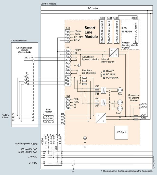
Connection example of a Smart Line Module
Опции
The table below lists the options available for Smart Line Modules (Details → Description of the options):
Available options | Order code |
|---|---|
CBC10 Communication Board | G20 1) |
CBE20 Communication Board | G33 1) |
AOP30 Advanced Operator Panel installed in the cabinet door | K08 1) |
CU320-2 DP Control Unit | K90 |
Performance expansion for CU320-2 | K94 1) |
Control Unit CU320‑2 PN | K95 |
Scope of delivery without line reactor | L22 |
Cabinet anti-condensation heating | L55 |
50/250 kW braking unit (can be used for frame size GB/GD) for line voltages of 380 … 480 V and 660 … 690 V | L62 |
50/250 kW braking unit (can be used for frame size GB/GD) for line voltages of 500 … 600 V | L65 |
Base 100 mm high, RAL 7022 | M06 |
Cable-marshalling space 200 mm high, RAL 7035 | M07 |
IP21 degree of protection | M21 |
IP23 degree of protection (includes M60) | M23 |
Side panel mounted at the right | M26 |
Side panel mounted at the left | M27 |
IP43 degree of protection (includes M60) | M43 |
IP54 degree of protection (includes M60) | M54 |
Closed cabinet door, air intake from below through floor opening | M59 |
Additional touch protection (included in M23, M43 and M54) | M60 |
DC busbar system (Id = 1170 A, 1 × 60 × 10 mm) | M80 |
DC busbar system (Id = 1500 A, 1 × 80 × 10 mm) | M81 |
DC busbar system (Id = 1840 A, 1 × 100 × 10 mm) | M82 |
DC busbar system (Id = 2150 A, 2 × 60 × 10 mm) | M83 |
DC busbar system (Id = 2730 A, 2 × 80 × 10 mm) | M84 |
DC busbar system (Id = 3320 A, 2 × 100 × 10 mm) | M85 |
DC busbar system (Id = 3720 A, 3 × 80 × 10 mm) | M86 |
DC busbar system (Id = 4480 A, 3 × 100 × 10 mm) | M87 |
Crane transport assembly (top-mounted) | M90 |
Special paint finish for cabinet | Y09 |
Factory assembly as transport units | Y11 |
One-line label for system identification, 40 × 80 mm | Y31 |
Two-line label for system identification, 40 × 180 mm | Y32 |
Four-line label for system identification, 40 × 180 mm | Y33 |
Customer documentation (circuit diagram, erminal diagram, layout diagram) in DXF format | D02 |
Preliminary version of customer documentation in PDF format | D14 |
Documentation in English/French | D58 |
Documentation in English/Spanish | D60 |
Documentation in English/Italian | D80 |
Without Operating Instructions | D99 |
Rating plate data in English/French | T58 |
Rating plate data in English/Spanish | T60 |
Rating plate data in English/Italian | T80 |
Visual acceptance | F03 |
Function test without connected motor | F71 |
Insulation test | F77 |
Customer-specific acceptance inspections (on request) | F97 |
1) Only together with option K90 or K95.
Option selection matrix for Smart Line Modules
Certain options can mutually exclude one another
(options that are not involved are not shown).
✓ | Possible combination |
|---|---|
– | Combination not possible |
Electrical options
| G20 | G33 | K90 | K95 |
|---|---|---|---|---|
G20 |
| – | ✓ | ✓ |
G33 | – |
| ✓ | ✓ |
K90 | ✓ | ✓ |
| – |
K95 | ✓ | ✓ | – |
|
Mechanical/electrical options
| M06 | M07 | M21 | M23 | M26 | M27 | M43 | M54 | M60 | M90 | Y11 | Y31 | Y32 | Y33 |
|---|---|---|---|---|---|---|---|---|---|---|---|---|---|---|
M06 |
| – | ✓ | ✓ | ✓ | ✓ | ✓ | ✓ | ✓ | ✓ | ✓ | ✓ | ✓ | ✓ |
M07 | – |
| ✓ | ✓ | ✓ | ✓ | ✓ | ✓ | ✓ | ✓ | ✓ | ✓ | ✓ | ✓ |
M21 | ✓ | ✓ |
| – | ✓ | ✓ | – | – | ✓ | ✓ | ✓ | ✓ | ✓ | ✓ |
M23 | ✓ | ✓ | – |
| ✓ | ✓ | – | – | – 1) | ✓ | ✓ | ✓ | ✓ | ✓ |
M26 | ✓ | ✓ | ✓ | ✓ |
| – | ✓ | ✓ | ✓ | ✓ | ✓ | ✓ | ✓ | ✓ |
M27 | ✓ | ✓ | ✓ | ✓ | – |
| ✓ | ✓ | ✓ | ✓ | ✓ | ✓ | ✓ | ✓ |
M43 | ✓ | ✓ | – | – | ✓ | ✓ |
| – | – 1) | ✓ | ✓ | ✓ | ✓ | ✓ |
M54 | ✓ | ✓ | – | – | ✓ | ✓ | – |
| – 1) | ✓ | ✓ | ✓ | ✓ | ✓ |
M60 | ✓ | ✓ | ✓ | – 1) | ✓ | ✓ | – 1) | – 1) |
| ✓ | ✓ | ✓ | ✓ | ✓ |
M90 | ✓ | ✓ | ✓ | ✓ | ✓ | ✓ | ✓ | ✓ | ✓ |
| – | ✓ | ✓ | ✓ |
Y11 | ✓ | ✓ | ✓ | ✓ | ✓ | ✓ | ✓ | ✓ | ✓ | – |
| ✓ | ✓ | ✓ |
Y31 | ✓ | ✓ | ✓ | ✓ | ✓ | ✓ | ✓ | ✓ | ✓ | ✓ | ✓ |
| – | – |
Y32 | ✓ | ✓ | ✓ | ✓ | ✓ | ✓ | ✓ | ✓ | ✓ | ✓ | ✓ | – |
| – |
Y33 | ✓ | ✓ | ✓ | ✓ | ✓ | ✓ | ✓ | ✓ | ✓ | ✓ | ✓ | – | – |
|
1) The option M60 is included in M23, M43 and M54.
DC busbar system mechanical options (busbars between individual Cabinet Modules)
| M80 | M81 | M82 | M83 | M84 | M85 | M86 | M87 |
|---|---|---|---|---|---|---|---|---|
M80 |
| – | – | ✓ | – | – | – | – |
M81 | – |
| – | – | ✓ | – | ✓ | – |
M82 | – | – |
| – | – | ✓ | – | ✓ |
M83 | ✓ | – | – |
| – | – | – | – |
M84 | – | ✓ | – | – |
| – | ✓ | – |
M85 | – | – | ✓ | – | – |
| – | ✓ |
M86 | – | ✓ | – | – | ✓ | – |
| – |
M87 | – | – | ✓ | – | – | ✓ | – |
|
Documentation
| D02 | D14 | D58 | D60 | D80 | D99 |
|---|---|---|---|---|---|---|
D02 |
| ✓ | ✓ | ✓ | ✓ | – |
D14 | ✓ |
| ✓ | ✓ | ✓ | – |
D58 | ✓ | ✓ |
| – | – | – |
D60 | ✓ | ✓ | – |
| – | – |
D80 | ✓ | ✓ | – | – |
| – |
D99 | – | – | – | – | – |
|
Rating plate data
| T58 | T60 | T80 |
|---|---|---|---|
T58 |
| – | – |
T60 | – |
| – |
T80 | – | – |
|
Технические данные
Line voltage 380 … 480 V 3 AC | Smart Line Modules | |||||
|---|---|---|---|---|---|---|
| 6SL3730-6TE35-5AA3 | 6SL3730-6TE37-3AA3 | 6SL3730-6TE41-1AA3 | 6SL3730-6TE41-3AA3 | 6SL3730-6TE41-7AA3 | |
For a parallel circuit configuration, mounted to the right at the Line Connection Module |
|
| 6SL3730-6TE41-1BA3 | 6SL3730-6TE41-3BA3 | 6SL3730-6TE41-7BA3 | |
For a parallel circuit configuration, mounted to the left at the Line Connection Module |
|
| 6SL3730-6TE41-1BC3 | 6SL3730-6TE41-3BC3 | 6SL3730-6TE41-7BC3 | |
Rated power | ||||||
| kW | 250 | 355 | 500 | 630 | 800 |
| kW | 235 | 315 | 450 | 555 | 730 |
| hp | 395 | 545 | 770 | 970 | 1230 |
| hp | 360 | 485 | 695 | 855 | 1125 |
DC link current | ||||||
| A | 550 | 730 | 1050 | 1300 | 1700 |
| A | 490 | 650 | 934 | 1157 | 1513 |
| A | 825 | 1095 | 1575 | 1950 | 2550 |
Infeed/regenerative feedback current | ||||||
| A | 463 | 614 | 883 | 1093 | 1430 |
| A | 694 | 921 | 1324 | 1639 | 2145 |
Current demand | ||||||
| A | 1.35 | 1.35 | 1.4 | 1.5 | 1.7 |
| A | 1.8 | 1.8 | 3.6 | 5.4 | 5.4 |
DC link capacitance | ||||||
| μF | 8400 | 12000 | 16800 | 18900 | 28800 |
| μF | 42000 | 60000 | 67200 | 75600 | 115200 |
Power loss, max. 3) | ||||||
| kW | 3.7 | 4.7 | 7.1 | 11.0 | 11.5 |
| kW | 3.7 | 4.7 | 7.1 | 11.0 | 11.5 |
Cooling air requirement | m3/s | 0.36 | 0.36 | 0.78 | 1.08 | 1.08 |
Sound pressure level LpA (1 m) at 50/60 Hz | dB | 69/73 | 69/73 | 70/73 | 70/73 | 70/73 |
PE/GND connection |
| PE bar | PE bar | PE bar | PE bar | PE bar |
| mm2 | 600 | 600 | 600 | 600 | 600 |
| mm2 | 240 | 240 | 240 | 240 | 240 |
Cable length, max. 4) | ||||||
| m | 4000 | 4000 | 4800 | 4800 | 4800 |
| m | 6000 | 6000 | 7200 | 7200 | 7200 |
Degree of protection |
| IP20 | IP20 | IP20 | IP20 | IP20 |
Dimensions | ||||||
| mm | 400 | 400 | 600 | 800 | 800 |
| mm | 2200 | 2200 | 2200 | 2200 | 2200 |
| mm | 600 | 600 | 600 | 600 | 600 |
Weight, approx. | kg | 270 | 270 | 490 | 775 | 775 |
Frame size |
| GX | GX | HX | JX | JX |
1) The base load current IH DC is the basis for a duty cycle of 150 % for 60 s or Imax DC for 5 s with a duty cycle duration of 300 s.
2) The current demand for the 400 V AC auxiliary power supply is drawn from the line input voltage.
3) The specified power loss represents the maximum value at 100 % utilization. The value is lower under normal operating conditions.
4) Sum of all motor cables and DC link. Longer cable lengths for specific configurations are available on request.
5) The cabinet height increases by 250 mm with IP21 degree of protection, and by 400 mm with IP23, IP43, IP54 degrees of protection.
Line voltage 500 … 690 V 3 AC | Smart Line Modules | ||||
|---|---|---|---|---|---|
| 6SL3730-6TG35-5AA3 | 6SL3730-6TG38-8AA3 | 6SL3730-6TG41-2AA3 | 6SL3730-6TG41-7AA3 | |
For a parallel circuit configuration, mounted to the right at the Line Connection Module |
| 6SL3730-6TG38-8BA3 | 6SL3730-6TG41-2BA3 | 6SL3730-6TG41-7BA3 | |
For a parallel circuit configuration, mounted to the left at the Line Connection Module |
| 6SL3730-6TG38-8BC3 | 6SL3730-6TG41-2BC3 | 6SL3730-6TG41-7BC3 | |
Rated power | |||||
| kW | 450 | 710 | 1000 | 1400 |
| kW | 405 | 665 | 885 | 1255 |
| kW |
Запрос коммерческого предложения× Сообщение отправлено× В ближайшее время сообщение будет обработано. Письмо с номером обращения отправлено на Ваш почтовый ящик. Спасибо за то, что выбрали Первый ZIP! Что-то пошло не так...× К сожалению, наша система расценила Ваше сообщение как спам. Если это произошло по ошибке, пожалуйста, обратитесь к нам по электронной почте. Приносим извинения за возможные неудобства.  Вы отправляете нам запрос  Если у нас есть прайс-лист, мы отправляем Вам ответ в течение дня. А если у нас нет прайс-листа по запрошенным товарам?     Если у нас нет прайс-листа, мы отправляем запрос производителю.  Ответ от производителя может занять до 5 дней и более. Ответ от производителя может занять до 5 дней и более.  Запрос производителю мы отправляем только для конечных потребителей.  Торгующим организациям коммерческие предложения предоставляются только по прайсовым позициям: Siemens Beckhoff Pepperl+Fuchs Phoenix Contact PILZ Turck Leuze Electronic Endress+Hauser Murr Elektronik Schmersal | |||