Technical description Siemens
Область применения
Power stations
Measurement of steam, condensate and water.
Petrochemical industry/Refineries
Measurement of water, steam and liquid and gas hydrocarbons.
Chemical industry
Measurement of various liquid and gas media.
Oil and gas industries
Measurement of liquid and gas hydrocarbons.
Обзор
Primary differential pressure devices are standardized mechanical flow sensors, often also referred to as differential pressure transducers. The primary differential pressure devices are calculated and manufactured according to DIN EN ISO 5167.
Through constriction of the line diameter in the pressure device, the flow rate creates a differential pressure that is converted with the help of a differential pressure transmitter into a proportional current signal or flow value. The assignment of differential pressure to flow is created by means of a "calculation of the primary differential pressure device".
Primary differential pressure devices are suitable for single-phase media such as gas, vapor and liquids without solid components.
Requirement when ordering a primary differential pressure device
Always quote the orifice plate calculation and the classification according to the pressure equipment directive 97/23/EC (PED) when placing an order.
Orifice plate calculation - calculation protocol
For the "orifice plate calculation" service, you need to fill out the "Questionnaire for calculation of a primary differential pressure device according to DIN EN ISO 5167". The intelligent "SITRANS F O questionnaire online" can be found in the PIA Life Cycle Portal at http://www.siemens.com/pia-portal.
For this purpose, you need to specify all the data of the measuring point, medium, process and pipe data, as well as details of installation conditions, flow conditions, permissible pressure losses and accuracy requirements.
We will be unable to carry out the calculation if there are any data missing. A calculation protocol with a consecutive number documents the calculation of the orifice plate. We require this calculation protocol from the customer for manufacturing purposes. It is to be included in the order for the orifice plate.
Important note:
The "Orifice Plate Calculation with Preparation of a Calculation Protocol" service is a separate process, and must be carried out before the orifice plate is ordered.
The calculation protocol issued by the customer is to be included in the order for the orifice plate.
Classification in accordance with pressure equipment directive 97/23/EC (PED)
The pressure equipment directive must also be applied to the Orifice portfolio for use in Europe.
In compliance with the pressure equipment directive, equipment is divided into categories I to III or Article 3 paragraph 3 according to danger potential (medium/pressure/volume/nominal diameter).
Submission of this design data in accordance with pressure equipment directive 97/23/EC is mandatory for ordering and manufacture, and must be specified by customers in the orifice plate order.
The Order No. of the orifice plate contains the relevant Category I, II, III or Article 3 paragraph 3 in the order code.
Detailed information is available under "Pressure equipment directive 97/23/EC".
How to order the "Orifice plate with appended calculation protocol" product
To order an orifice plate, you need to supply the following data:
- Complete Order No. of the orifice plate, including the respective order code "Manufacture according to pressure equipment directive":
- Category I, II, III or Article 3 paragraph 3 and the design data with Order Codes Y31 to Y35
- Or without (only available outside Europe!)
- Appended "Calculation Protocol" issued by the customer with Order Code Y21 or Y22, or statement "Orifice plate without calculation" with Order Code Y01
The orifice plate can only be manufactured when it has been passed as a "clean order", i. e. it has been confirmed that the data of the Order No. match the data of the calculation protocol.
Дизайн
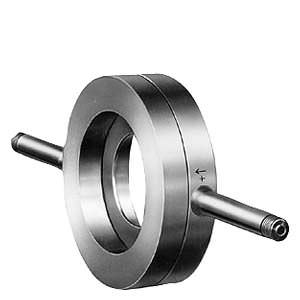
Orifice plate with annular chambers
The version orifice plate with annular chambers comprises two support rings which are connected to the inside of the pipe over an annular chamber and an annular gap. Tapping sockets direct the differential pressure from the support rings to the differential pressure transmitter over shut-off fittings and differential pressure lines.
The orifice disk is inserted between the support rings together with a gasket.
Orifice plate with single tappings
In the version of the orifice plate with single tappings the orifice plate is a single unit. The inside of the tube is connected to the tapping sockets by two single tappings.
Both types of orifice plate are installed between two flanges in the pipeline.
Характеристика
The orifice plate has a square-law relationship between differential pressure and flow. A square-root transmitter is required therefore to create a linear flow characteristic.

Relationship between flow q and differential pressure Δp
Функции
Mode of operation
The orifice plate creates a differential pressure. The pressure is transferred through the vertical columns of medium in the differential pressure lines to the measuring cell of the differential pressure transmitter. The transmitter converts the pressure signal with square-root characteristic into a flow-proportional current or into a digital signal, e. g. PROFIBUS.
Types of primary differential pressure devices
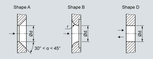
Shapes of the orifice disk aperture
The primary differential pressure devices are calculated and manufactured according to DIN EN ISO 5167. According to this, the application range of the standard orifice disk aperture form A is limited by the Reynolds number. The limits depend on the diameter ratio β = d/D. (D: internal diameter of pipe).
In the case of Reynolds numbers from approx. 500 to 2.5 x 10⁵ and DN 40 to DN 150, the orifice disk aperture form B (quarter circle) can be used for slightly less accurate measurements. The profile radius r depends on the diameter ratio ß and results from the calculation of the diameter of the orifice disk aperture d.
The cylindrical orifice disk aperture form D is used for measurements in both flow directions.
Tapping sockets
Type of threaded connections and welding connections dependent on the measured medium and the nominal pressure of the shut-off fitting
The type of socket connections depends on the measured medium and the nominal pressure of the shut-off fittings; the socket length depends on the nominal diameter (pipe diameter) of the primary differential pressure device and the operating temperature (because of the thermal insulation!). The socket position depends on the measured medium and the flow direction.
- With threaded connection G½ DIN ISO 228/1, connection dimensions to DIN 19207 Form V, for liquids and gases up to PN 160, for steam up to PN 100
- With threaded connection ½-14 NPT male, for version acc. to ASME up to class 600
- With Ø 12 mm pipe connection for pipe union with ferrule
- With Ø 21.3 mm welding connection for liquids and gases up to PN 400, and for steam up to PN 100, or Ø 24 mm for liquids and gases over PN 400, and for steam over PN 100
Other connections on request.
Length of tapping sockets
The length of the tapping sockets are specified in DIN 19205, Part 2.
If using with high temperatures and stronger insulations, please quote the insulation thickness and the required length of the tapping sockets when placing an order.
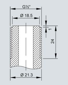
Threaded connections of tapping sockets for liquids and gases up to PN 160, for steam up to PN 100, dimensions in mm
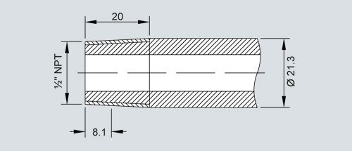
Threaded connection ½-14 NPT male, dimensions in mm

With Ø 12 mm pipe for pipe union with ferrule, dimensions in mm
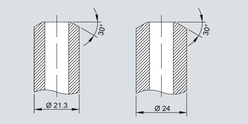
Welding connections of tapping sockets, dimensions in mm
Position of the tapping sockets
When measuring liquids and gases, the position of the tapping sockets must comply with the tables according to DIN 19205; when measuring steam, the compensation vessels must be at the same height.
- Horizontal steam lines
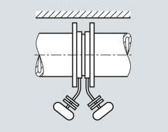
Horizontal steam line in front of a wall with primary differential pressure device and valve combination; with annular chamber orifice plate or single part orifice plate with special length of 65 mm
In the case of horizontal steam lines, straight sockets are arranged opposite each other or, if the pipe is close to a wall, with bent sockets on one side.
- Vertical steam lines
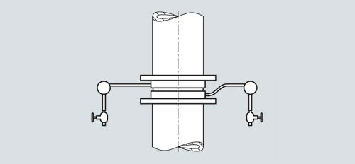
Vertical steam line with primary differential pressure device and valve combination
In the case of vertical and inclined steam lines, the lower socket is bent upwards so that the connection flanges and compensation vessels are also at the same height.
Extract from DIN 19205, Part 1, August 1988
No. | Pipe position and flow direction | Position of the tapping sockets | Application | |||
|---|---|---|---|---|---|---|
1 | Horizontal | → | 180° | 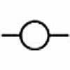 | With compensation vessels | |
2 1)2) | 0° | 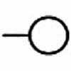 | ||||
3 1) 2) | 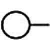 | |||||
4 | Vertical | Rising | ↑ | 90° |  | |
5 | Setpoint direction falling | ↓ | ||||
6 | Rising | ↑ | 180° |  | ||
7 | Setpoint direction falling | ↓ | ||||
10 | Horizontal | → | < Запрос коммерческого предложения× Сообщение отправлено× В ближайшее время сообщение будет обработано. Письмо с номером обращения отправлено на Ваш почтовый ящик. Спасибо за то, что выбрали Первый ZIP! Что-то пошло не так...× К сожалению, наша система расценила Ваше сообщение как спам. Если это произошло по ошибке, пожалуйста, обратитесь к нам по электронной почте. Приносим извинения за возможные неудобства. | |||


 Ответ от производителя может занять до 5 дней и более.

