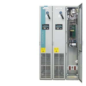
Central Braking Modules Siemens
Обзор
Central Braking Modules limit the DC link voltage at a central location in the drive line-up when the motors are operating in generator mode and energy recovery to the supply system is not possible. If the voltage of the DC busbar exceeds a limit value in generator operation, an externally installed braking resistor is switched in, thus restricting the voltage from increasing further. The regenerative energy is converted into heat. The braking resistor is switched in by the Braking Unit integrated in the Cabinet Module, which is equipped with state-of-the-art MOSFET/IGBT semiconductors.
Central Braking Modules are an alternative to the optional Braking Modules (options L61/L62 or L64/L65) and are particularly suitable when high braking powers are required in a drive lineup. The required braking power can also be increased by connecting units in parallel.
Line voltage | Line voltage | Braking power P150 |
|---|---|---|
380 … 480 V 3 AC | 510 … 720 V DC | 500 kW / 1000 kW |
500 … 600 V 3 AC | 675 … 900 V DC | 550 kW / 1100 kW |
660 … 690 V 3 AC | 890 … 1035 V DC | 630 kW / 1200 kW |
Central Braking Modules operate as fully stand-alone modules. They only require a connection to the DC link. An external control voltage is not required.
The built-in fan means that Central Braking Modules are also suitable for high continuous power levels.
Дизайн
The Central Braking Module is a cabinet unit with integrated braking chopper. Using state-of-the-art MOSFET/IGBT semiconductors, the power unit controls when the braking resistor is switched-in.
Central Braking Modules are designed as a 400 mm wide cabinet module. The connection to the DC link busbars is established through fuses.
Central Braking Modules require braking resistors that must be externally mounted and which can be ordered separately. The cables to the resistors can be connected to lugs which are specially prepared for plant application and which are located in the connection area of the cabinet.
The power units have diagnostics LEDs for the display of faults and also a control output for the communication of faults. The Central Braking Module can be disabled externally via a control input.
The engineering specifications must be applied regarding the arrangement in the DC link line-up. For additional information, please refer to the SINAMICS Low Voltage Engineering Manual.
Характеристика
Central Braking Modules are dimensioned for braking powers with the following duty cycles:
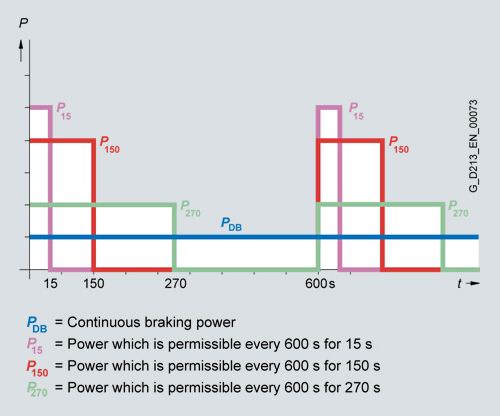
Braking powers of the Central Braking Modules
The braking powers are subject to a cycle time of 600 s. P150 is assumed to be the rated braking power. The braking resistors can be assigned according to these power ratings.
In most applications, Central Braking Modules are only used for occasional braking operations, e.g. stopping a drive in an emergency. Low-cost braking resistors in IP21 degree of protection are specifically offered for these types of applications; these braking resistors are dimensioned for braking powers PBR with the following duty cycle:
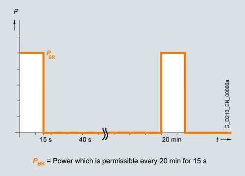
Duty cycle for braking resistors
Braking resistors with a higher braking power and shorter cycle times are available on request.
Интеграция
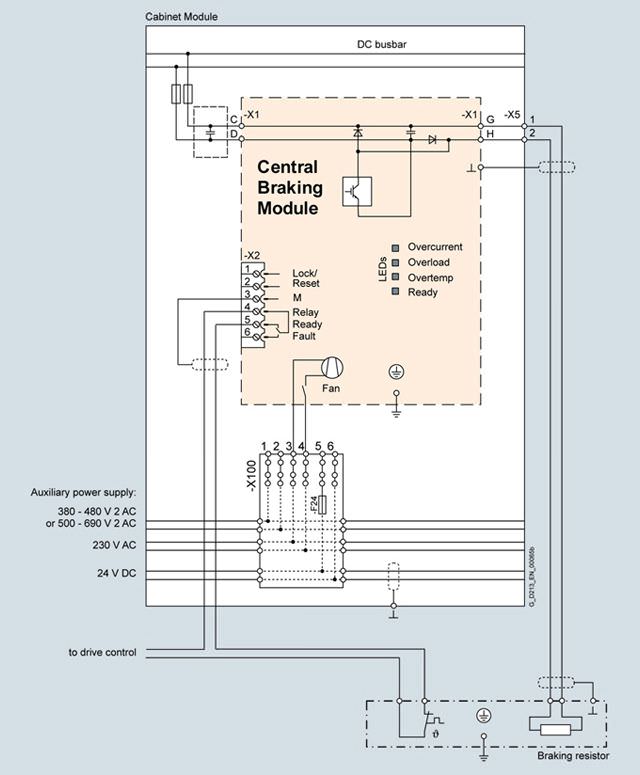
Example of connection of a Central Braking Module
Опции
The following options are available for the Central Braking Modules:
Available options | Order code |
|---|---|
Cabinet anti-condensation heating | L55 |
Base 100 mm high, RAL 7022 | M06 |
Cable-marshalling space 200 mm high, RAL 7035 | M07 |
IP21 degree of protection | M21 |
IP23 degree of protection | M23 |
Side panel mounted at the right | M26 |
Side panel mounted at the left | M27 |
IP43 degree of protection | M43 |
IP54 degree of protection | M54 |
Closed cabinet door, air intake from below through floor opening | M59 |
DC busbar system (Id = 1170 A, 1 × 60 × 10 mm) | M80 |
DC busbar system (Id = 1500 A, 1 × 80 × 10 mm) | M81 |
DC busbar system (Id = 1840 A, 1 × 100 × 10 mm) | M82 |
DC busbar system (Id = 2150 A, 2 × 60 × 10 mm) | M83 |
DC busbar system (Id = 2730 A, 2 × 80 × 10 mm) | M84 |
DC busbar system (Id = 3320 A, 2 × 100 × 10 mm) | M85 |
DC busbar system (Id = 3720 A, 3 × 80 × 10 mm) | M86 |
DC busbar system (Id = 4480 A, 3 × 100 × 10 mm) | M87 |
Crane transport assembly (top-mounted) | M90 |
Special paint finish for cabinet | Y09 |
Factory assembly as transport units | Y11 |
One-line label for system identification, 40 × 80 mm | Y31 |
Two-line label for system identification, 40 × 180 mm | Y32 |
Four-line label for system identification, 40 × 180 mm | Y33 |
Customer documentation (circuit diagram, terminal diagram, layout diagram) in DXF format | D02 |
Preliminary version of customer documentation in PDF format | D14 |
Documentation in English/French | D58 |
Documentation in English/Spanish | D60 |
Documentation in English/Italian | D80 |
Without Operating Instructions | D99 |
Rating plate data in English/French | T58 |
Rating plate data in English/Spanish | T60 |
Rating plate data in English/Italian | T80 |
Visual acceptance | F03 |
Function test without connected motor | F71 |
Insulation test | F77 |
Customer-specific acceptance inspections (on request) | F97 |
Option selection matrix for Central Braking Modules
Certain options can mutually exclude one another
(options that are not involved are not shown).
✓ | Possible combination |
|---|---|
– | Combination not possible |
Mechanical/electrical options
| M06 | M07 | M21 | M23 | M26 | M27 | M43 | M54 | M90 | Y11 | Y31 | Y32 | Y33 |
|---|---|---|---|---|---|---|---|---|---|---|---|---|---|
M06 |
| – | ✓ | ✓ | ✓ | ✓ | ✓ | ✓ | ✓ | ✓ | ✓ | ✓ | ✓ |
M07 | – |
| ✓ | ✓ | ✓ | ✓ | ✓ | ✓ | ✓ | ✓ | ✓ | ✓ | ✓ |
M21 | ✓ | ✓ |
| – | ✓ | ✓ | – | – | ✓ | ✓ | ✓ | ✓ | ✓ |
M23 | ✓ | ✓ | – |
| ✓ | ✓ | – | – | ✓ | ✓ | ✓ | ✓ | ✓ |
M26 | ✓ | ✓ | ✓ | ✓ |
| – | ✓ | ✓ | ✓ | ✓ | ✓ | ✓ | ✓ |
M27 | ✓ | ✓ | ✓ | ✓ | – |
| ✓ | ✓ | ✓ | ✓ | ✓ | ✓ | ✓ |
M43 | ✓ | ✓ | – | – | ✓ | ✓ |
| – | ✓ | ✓ | ✓ | ✓ | ✓ |
M54 | ✓ | ✓ | – | – | ✓ | ✓ | – |
| ✓ | ✓ | ✓ | ✓ | ✓ |
M90 | ✓ | ✓ | ✓ | ✓ | ✓ | ✓ | ✓ | ✓ |
| – | ✓ | ✓ | ✓ |
Y11 | ✓ | ✓ | ✓ | ✓ | ✓ | ✓ | ✓ | ✓ | – |
| ✓ | ✓ | ✓ |
Y31 | ✓ | ✓ | ✓ | ✓ | ✓ | ✓ | ✓ | ✓ | ✓ | ✓ |
| – | – |
Y32 | ✓ | ✓ | ✓ | ✓ | ✓ | ✓ | ✓ | ✓ | ✓ | ✓ | – |
| – |
Y33 | ✓ | ✓ | ✓ | ✓ | ✓ | ✓ | ✓ | ✓ | ✓ | ✓ | – | – |
|
Mechanical options, DC busbar (busbars between individual Cabinet Modules)
| M80 | M81 | M82 | M83 | M84 | M85 | M86 | M87 |
|---|---|---|---|---|---|---|---|---|
M80 |
| – | – | ✓ | – | – | – | – |
M81 | – |
| – | – | ✓ | – | ✓ | – |
M82 | – | – |
| – | – | ✓ | – | ✓ |
M83 | ✓ | – | – |
| – | – | – | – |
M84 | – | ✓ | – | – |
| – | ✓ | – |
M85 | – | – | ✓ | – | – |
| – | ✓ |
M86 | – | ✓ | – | – | ✓ | – |
| – |
M87 | – | – | ✓ | – | – | ✓ | – |
|
Documentation
| D02 | D14 | D58 | D60 | D80 | D99 |
|---|---|---|---|---|---|---|
D02 |
| ✓ | ✓ | ✓ | ✓ | – |
D14 | ✓ |
| ✓ | ✓ | ✓ | – |
D58 | ✓ | ✓ |
| – | – | – |
D60 | ✓ | ✓ | – |
| – | – |
D80 | ✓ | ✓ | – | – |
| – |
D99 | – | – | – | – | – |
|
Rating plate data
| T58 | T60 | T80 |
|---|---|---|---|
T58 |
| – | – |
T60 | – |
| – |
T80 | – | – |
|
Технические данные
| Central Braking Modules | ||||||
|---|---|---|---|---|---|---|---|
| 6SL3700-1AE35-0AA3 | 6SL3700-1AE41-0AA3 | 6SL3700-1AF35-5AA3 | 6SL3700-1AF41-1AA3 | 6SL3700-1AH36-3AA3 | 6SL3700-1AH41-2AA3 | |
Line voltage | 380 … 480 V | 500 … 600 V | 660 … 690 V | ||||
Braking power P150 | kW | 500 | 1000 | 550 | 1100 | 630 | 1200 |
Continuous braking power PDB | kW | 200 | 370 | 220 | 420 | 240 | 460 |
Braking current for P150 | A | 650 | 1200 | 580 | 1100 | 520 | 1000 |
Current demand 1) | |||||||
| A | 0.4 | 0.4 | 0.4 | 0.4 | 0.4 | 0.4 |
Power loss, max. 2) at 50 Hz 400/500/690 V | kW | 0.8 | 1.5 | 0.8 | 1.5 | 0.8 | 1.5 |
DC link capacitance | μF | 8160 | 9720 | 7640 | 8680 | 7640 | 8680 |
Cooling air requirement | m3/s | 0.14 | 0.14 | 0.14 | 0.14 | 0.14 | 0.14 |
Sound pressure level LpA (1 m) at 50/60 Hz | dB | 55 | 55 | 55 | 55 | 55 | 55 |
Braking resistor connection terminal |
| M12 screws | M12 screws | M12 screws | M12 screws | M12 screws | M12 screws |
| mm2 | 2 × 240 | 2 × 240 | 2 × 240 | 2 × 240 | 2 × 240 | 2 × 240 |
PE/GND connection |
| PE bar | PE bar | PE bar | PE bar | PE bar | PE bar |
| mm2 | 600 | 600 | 600 | 600 | 600 | 600 |
| mm2 | 240 | 240 | 240 | 240 | 240 | 240 |
Degree of protection |
| IP20 | IP20 | IP20 | IP20 | IP20 | IP20 |
Dimensions | |||||||
| mm | 400 | 400 | 400 | 400 | 400 | 400 |
| mm | 2200 | 2200 | 2200 | 2200 | 2200 | 2200 |
| mm | 600 | 600 | 600 | 600 | 600 | 600 |
Weight, approx. | kg | 230 | 230 | 230 | 230 | 230 | 230 |
Frame size | mm | 400 | 400 | 400 | 400 | 400 | 400 |
1) Current demand of the fans.
2) The specified power loss represents the maximum value at 100 % utilization. The value is lower under normal operating conditions.
3) The cabinet height increases by 250 mm with IP21 degree of protection, and by 400 mm with IP23, IP43 and IP54 degrees of protection.
| Braking resistors | ||||||
|---|---|---|---|---|---|---|---|
| 6SL3000-1BE35-0AA0 | 6SL3000-1BE41-0AA0 | 6SL3000-1BF35-5AA0 | 6SL3000-1BF41-1AA0 | 6SL3000-1BH36-3AA0 | 6SL3000-1BH41-2AA0 | |
Line voltage | 380 … 480 V | 500 … 600 V | 660 … 690 V | ||||
Braking power PBR | kW | 500 | 1000 | 550 | 1100 | 630 | 1200 |
Continuous braking power PDB | kW | 23 | 58 | 34 | 62 | 42 | 75 |
Resistance value | Ω | 0.95 | 0.49 | 1.35 | 0.69 | 1.8 | 0.95 |
Degree of protection |
| IP21 | IP21 | IP21 | IP21 | IP21 | IP21 |
Dimensions | |||||||
| mm | 960 | 960 | 960 | 960 | 960 | 960 |
| mm | 620 | 620 | 620 | 620 | 620 | 620 |
| mm | 790 | 1430 | 1110 | 1430 | 1110 | 1430 |
Weight, approx. | kg | 82 | 170 | 110 | 180 | 124 | 196 |


 Ответ от производителя может занять до 5 дней и более.

