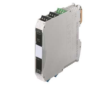
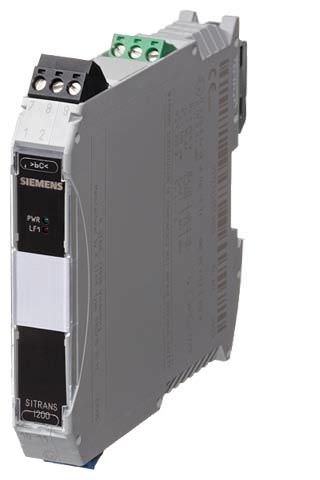
SITRANS I200, output isolator Siemens
Обзор
Analog output 0/4 to 20 mA
The output isolators are used for intrinsically-safe operation of valve positioners, i/p converters or indicators.
Operation of intrinsically-safe HART valve positioners (e.g. SIPART PS2) is also possible. The units transfer a superimposed HART communication signal bidirectionally.
Дизайн
The isolating transformer HART consists of a compact plastic housing (IP30) and is equipped with push-in screw terminals.
On the front are a green LED for indicating the power supply status and a red LED for signaling errors.
The auxiliary power supply can be connected individually using push-in screw terminals or jointly for up to 40 units using pac-Bus.

SITRANS I200 output isolator, function block diagram
Чертеж
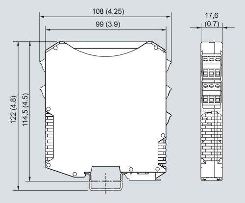
SITRANS I200 output isolator with HART, dimensions in mm (inch)
Особенности
- For HART output signals 0/4 to 20 mA
- Intrinsically safe output [Ex ia] IIC
- Electrical isolation between input, output and auxiliary power
- Open-circuit and short-circuit monitoring and messaging (can be switched off)
- Installation possible in Zone 2 and Div. 2
- Can be used up to SIL 2 (IEC 61508)
Zones | ||||||
|---|---|---|---|---|---|---|
0 | 1 | 2 | 20 | 21 | 22 | |
Ex i interfaces | X | X | X | X | X | X |
Installation in | X | X | ||||
Схема подключения
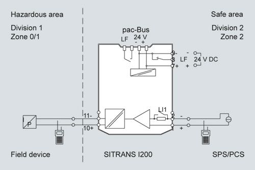
SITRANS I200 output isolator with HART, connection diagram
Технические данные
SITRANS I200 output isolator with HART | |
Input | |
Input signal | 0/4 ... 20 mA with HART |
Functional range | 0 ... 24 mA |
Max. input current | 50 mA |
Input resistance (changeable switch LI) | 225 Ω/550 Ω |
Communication signal | Bidirectional HART transmission, 0.5 kHz ... 30 kHz |
Ex i output | |
Output signal | 0/4 ... 20 mA with HART |
Connectable load resistance | 0 ... 800 Ω |
Min. load resistance for short-circuit monitoring | 150 Ω |
Residual ripple | ≤ 50 mV |
No-load voltage | ≤ 25.6 V |
Response time (10% ... 90%) | ≤ 100 μs |
Transmission characteristics | 1:1 |
Measuring accuracy Accuracy, typical data expressed as % of calibrated span at UN, 23 °C | |
Linearity error | ≤ 0.1% |
Offset error | ≤ 0.1% |
Temperature influence | ≤ 0.1%/10 K |
Power supply effect within voltage range | ≤ 0.01% |
Load resistance effect | ≤ 0.02% |
Rated conditions | |
Degree of protection of enclosure | IP30 |
Degree of protection of terminals | IP20 |
Ambient conditions | |
| -20 °C ... +70 °C (-4 ... +158 °F) |
| -40 °C ... +80 °C (-40 ... +176 °F) |
| ≤ 95% |
Electromagnetic compatibility | Tested under the following standards and regulations: EN 61326-1 Use in the industrial environment |
Design | |
Screw terminals | |
| |
| 0.2 ... 2.5 mm2 (0.00031 ... 0.0039 in2) |
| 0.2 ... 2.5 mm2 (0.00031 ... 0.0039 in2) |
| 0.25 ... 2.5 mm2 (0.00039 ... 0.0039 in2) |
| |
| 0.2 ... 1 mm2 (0.00031 ... 0.00155 in2) |
| 0.2 ... 1.5 mm2 (0.00031 ... 0.0023 in2) |
| 0.25 ... 1 mm2 (0.00039 ... 0.00155 in2) |
Weight | Approx. 160 g (0.35 lb) |
Type of installation | On DIN rail according to EN 50022 (NS35/15; NS35/7.5) |
Mounting position | Vertical or horizontal |
Enclosure material | PA 6.6 |
Fire protecting class (UL-94) | V0 |
Auxiliary power | |
Rated voltage UN | 24 V DC |
Voltage range | 18 ... 31.2 V |
Residual ripple within voltage range | ≤ 3.6 VSS |
Rated current (UN, 20 mA) | 80 mA |
Power consumption (UN, 20 mA) | 1.3 W |
Power loss (at UN, RL = 500 Ω) | 1.1 W |
Operation indicator | Green "PWR" LED |
Reverse polarity protection | Yes |
Undervoltage monitoring | Yes (no faulty module/output states) |
Electrical isolation | |
| |
| 1.5 kV AC |
| 1.5 kV AC |
| 1.5 kV AC |
| |
| 350 V AC |
| 350 V AC |
Error detection Ex i output | |
| > 10 kΩ |
| < 15 Ω |
| > 100 kΩ |
| ≥ 3.6 mA |
| Activated/deactivated |
| LED red "LF" |
|
|
Certificates and approvals | |
Explosion protection ATEX | |
| DMT 03 ATEX E 012 X |
| II 3 (1) G Ex nA nC [ia] IIC T4 II (1) D [Ex iaD] |
Installation | In Zone 2, Div. 2 and in the safe area |
Other approvals | USA (FM) Canada (CSA) Shipping (DNV) |
Safety specifications (CENELEC) | |
| 25.6 V |
| 96 mA |
| 605 mW |
| 103 nF/800 nF |
| 1.9 mH/11 mH |
| Negligible |
| 253 V |
| See Certifications |


 Ответ от производителя может занять до 5 дней и более.

