Base unit Siemens
Область применения
Application areas
Depending on the analyzer modules installed, the device is predominantly used in the following sectors:
- Chemical industry
- Petrochemicals
- Steel
- Cement
- Power generation
- Environmental protection
Обзор
The entire SIPROCESS GA700 device is configured in a modular fashion and consists of a base unit and at least one – maximum two – analyzer modules. It can optionally be fitted with up to two interface modules.
Дизайн
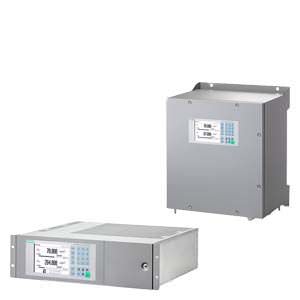
19" rack unit
- 19" rack unit with 3 height units (HU) for installation
- in hinged frames
- in cabinets with or without telescopic rails
- Gas connections for sample gas inlet and outlet: for pipe diameter 6 mm
- Purging gas connections (optional), purging gas connection for 6 mm or 1/4" hose (optional)
Wall-mounted device
- Gas connections for sample gas inlet and outlet: Pipe union for pipe diameter 6 mm (directly on the analyzer modules)
- Purging gas connections: Pipe diameter 12 mm
Display and operator panel
- LCD panel for simultaneous display of:
- Measured value
- Status line
- Measuring ranges
- Menu-driven operation for parameterization, test functions, adjustment
- Operator support in plain text
- Operating software (10 languages)
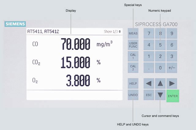
Display and operator panel of the SIPROCESS GA700 devices
Inputs and outputs
- 8 binary inputs, designed for 24 V, floating, freely configurable (e.g. for measurement range switchover, processing of external signals from sample preparation)
- 8 relay outputs, with changeover contacts, freely configurable (e.g. for faults, maintenance requests, limit alarms, external solenoid valves)
- Ethernet connection contained in the base unit (connection on the rear side, Ethernet RJ 45, 100 MBit)
- Service interface (front side); Ethernet RJ 45, 100 MBit.
Interface modules
- Interface module 1.1:
Adds 8 inputs and 12 outputs to the digital interfaces of the base unit.
- Interface module 2.1:
One analog output per measured component (max. 6, 0 to 20 mA, 4 to 20 mA or parameterizable according to NAMUR), plus 6 digital outputs
- Interface Module 2.2:
Three analog outputs and two analogue inputs per analyzer module, plus 4 digital inputs.
Функции
Essential characteristics
- Measuring range identification
- Storage of measured values possible during adjustments
- Four freely parameterizable measuring ranges, also with suppressed zero point
- Autoranging possible; remote switching is also possible
- Wide range of selectable time constants (static/dynamic noise suppression); i.e. the response time of the analyzer can be matched to the respective measuring task
- Measuring point switchover for up to 12 measuring points (programmable)
- Parameterizable measuring point identification
- Automatic, parameterizable measuring range calibration
- Operation based on the NAMUR recommendation
- Three control levels with their own authorization codes for the prevention of accidental and unauthorized operator interventions
- Simple handling using a numerical membrane keyboard and operator prompting
- Customer-specific analyzer options such as:
- Customer acceptance
- TAG labels
Чертеж
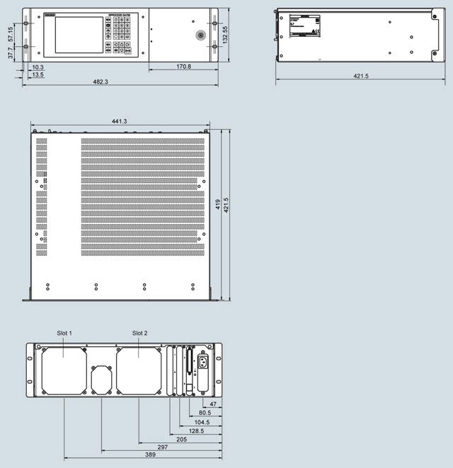
SIPROCESS GA700, rack unit, dimensions in mm
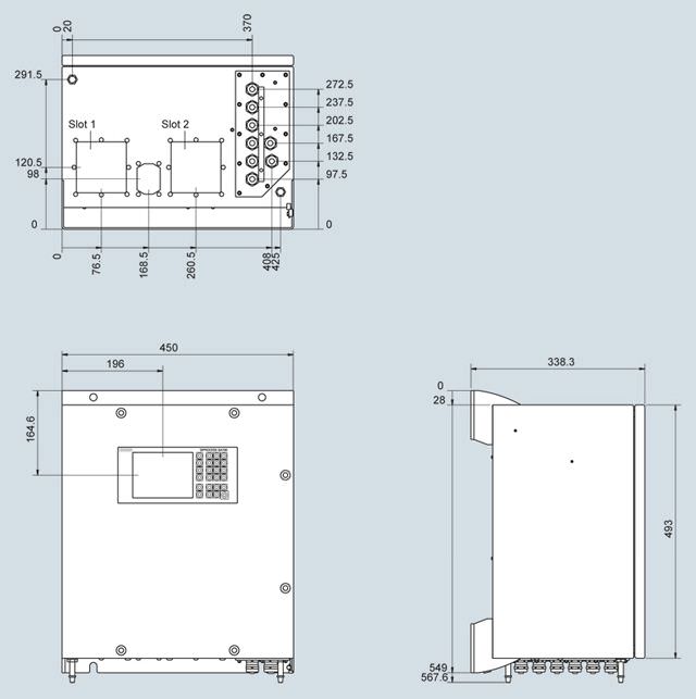
SIPROCESS GA700, wall housing, dimensions in mm
Особенности
The base unit provides:
- Transmission and evaluation of measurement results
- Display and transmission of device parameters
- Operation (parameterization, configuration)
In addition to the analyzer modules, the base unit contains the interfaces for the peripherals.
Схема подключения
Connection of the signal cables
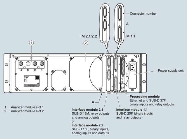
Expansion options for processing and interface modules with the example of the rear wall of the rack unit
Possible combinations
You can install a maximum of two analyzer modules in the enclosure of SIPROCESS GA700 series. These fixed allocation rules apply: Not every module can be operated in every slot. The following compatibility matrix gives you an overview of the possible combinations:
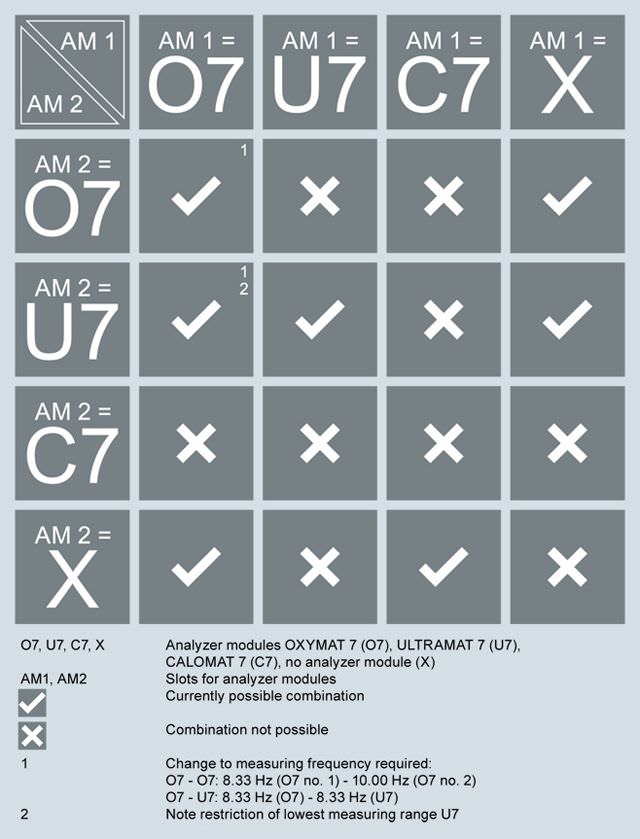
Compatibility matrix analyzer modules ↔ slots
Examples of possible combinations:
- A CALOMAT 7 analyzer module can only be used in Slot 1. Combination with other modules is not permitted.
- Combination: OXYMAT 7 analyzer module in Slot 1 and ULTRAMAT 7 analyzer module in Slot 2
- 1st ULTRAMAT 7 analyzer module in Slot 1, 2nd ULTRAMAT 7 analyzer module in Slot 2
Технические данные
19" rack unit | Wall enclosure | |
General information | ||
Operating position | Horizontal | Vertical |
Conformity | CE mark in accordance with EN 50081-1 and EN 50082-2 | |
Design, enclosure | ||
Weight without module | 8.6 kg | 23 kg |
Degree of protection | IP20 according to EN 60529 | IP65 in accordance with EN 60529, |
Electrical characteristics | ||
Auxiliary power | 100 ... 240 V AC (nominal range of use 85 ... 264 V), 50 ... 60 Hz (nominal range of use 47 ... 63 Hz) | |
Power consumption | Max. 280 VA | |
EMC interference immunity (electromagnetic compatibility) | In accordance with the standard requirements of NAMUR NE21 (05/2006) and EN 61326-1 (2013) | |
Electrical safety | In accordance with EN 61010-1, overvoltage category II | |
Gas inlet conditions, purging gas pressure | ||
Continuous (recommended) | - | 30 hPa above atmospheric pressure |
Continuous (maximum) | - | < 100 hPa above atmospheric pressure |
Transient (maximum) | - | 165 hPa above atmospheric pressure |
Electrical inputs and outputs | ||
Relay outputs | 8, with changeover contacts, can be freely parameterized, e.g. for measuring range identification; max. load: 24 V AC/DC/1.7 A (total load for all 8 relay outputs in continuous operation max. 160 W), floating, non-sparking | |
Binary inputs | 8, designed for 24 V, floating, can be freely parameterized, e.g. for measurement range switchover | |
Ethernet interface Ethernet RJ 45, 100-megabit | Rear | Underside |
Service interface Ethernet RJ 45, 100-megabit | Front | Inside on the processing unit |
Interface module 1.1 | 12 digital outputs, with changeover contacts, load rating: 24 V AC/DC/1.7 A (total load for all 12 relay outputs in continuous operation max. 244 W), floating, non-sparking 8 digital inputs, designed for 24 V, floating, freely parameterizable | |
Interface module 2.1 | 6 analog outputs 0/4 to 20 mA, floating; burden 100 Ω ≤ RL ≤ 750 Ω; 6 digital outputs, load rating: 24 V AC/DC/1.7 A (total load for all 6 relay outputs in continuous operation max. 122 W), floating, non-sparking | |
Interface module 2.2 | 6 analog outputs 0/4 to 20 mA, floating; burden 100 Ω ≤ RL ≤ 750 Ω; 4 analog inputs 0/4 … 20 mA, non-isolated, internal resistance ≤ 100 Ω 4 digital inputs, designed for 24 V, floating | |
Climatic conditions | ||
Permissible operating altitude | 3 000 m above sea level | |
Permissible ambient temperature | Depends on application, See technical specifications of the analyzer module Ventilation slits must not be covered (recommended minimum clearance upward from the next device when installing 2 analyzer modules and at maximum ambient temperature: min. 1 HU) | Depends on application, See technical specifications of the analyzer module |
Permissible humidity | < 90% RH (RH: relative humidity), during storage, transportation and operation (must not fall below dew point) | |


 Ответ от производителя может занять до 5 дней и более.

