SIPROCESS UV600 Siemens
Область применения
Fields of application
- Emission measurements
- Measurement of low NO concentrations in power plants or gas turbines
- Monitoring of NOx in denitrification plants by direct measurement of NO and NO2, as well as summation to NOx in the analyzer
- Efficient measurement in desulfurization plants
- Monitoring of very small SO2 and NO concentrations
- Emission measurements in the paper and cellulose industries
- Process monitoring
- Measurement of SO2 in process gases in the paper and petrochemical industries
- Optimization of NOx emissions in exhaust gas in the automotive industry
- H2S measurement
- In typical emission applications
- Taking account of possible cross-sensitivities (e.g. from mercaptan)
Special versions
Special applications
In addition to the standard combinations, special applications are also available upon request, e.g. as regards the material in the gas path and the sample chambers.
Обзор
The function of the SIPROCESS UV600 gas analyzer is based on UV resonance absorption spectrometry. It also is used to measure very low NO, NO 2, SO2 or H2S concentrations in gases.
Дизайн
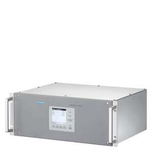
- 19" rack unit with 4 HU for installation
- in hinged frame
- in cabinets with or without telescopic rails
- Internal gas paths: hose made of FKM (VitonTM) or pipe made of PTFE or stainless steel
- Gas connections for sample gas inlet and outlet and for reference gas: fittings, pipe diameter of 6 mm or ¼"
Display and control panel
- Large LCD panel for simultaneous display of measured value and device status
- Sensor buttons with context-based functions
- Display protected by glass pane
- Contrast of the LC display can be adjusted
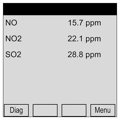
SIPROCESS UV600, display and control panel
Inputs and outputs
- 2 configurable analog inputs
- 4 configurable analog outputs
- 8 digital inputs
- 8 digital outputs
Communications
Connection via SIPROCESS-UV600-specific software tool
Materials wetted by sample gas
Component | Material |
|---|---|
Analyzer unit (sample chamber) | Aluminum or stainless steel mat. no. 1.44041), epoxy resin |
Optical window | CaF2 or quartz1), epoxy resin |
Gas path, gaskets | FKM (Viton), PTFE, stainless steel mat. no. 1.45711) |
Chamber | Aluminum or stainless steel1) |
Gas inlet/outlet | PVDF, stainless steel, mat. no. 1.44011) |
Moisture sensor | Stainless steel mat. no. 1.4571, platinum, epoxy resin |
Diaphragm pump | |
| PVDF |
| FKM (Viton), EPDM |
1) Depending on the version
Gas flow chart
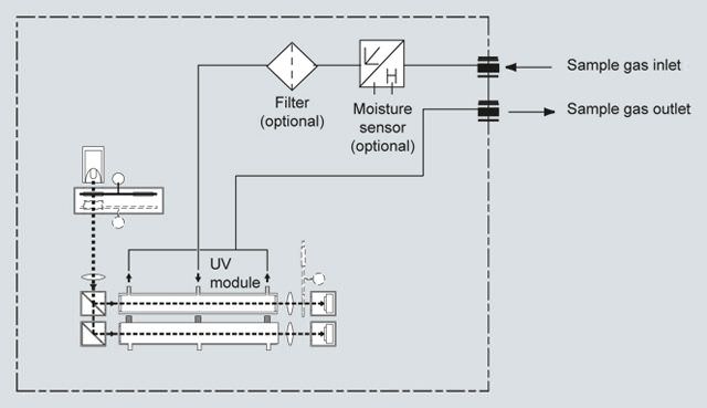
SIPROCESS UV600, gas flow chart
Способ действия
The measuring principle of the SIPROCESS UV600 is based on the molecule-specific absorption of gases in the ultraviolet wavelength range. Radiation of a wavelength appropriate to the measurement is passed through the sample, and the selective absorption which is proportional to the concentration of the measured component is determined.
Measuring method
An electrodeless discharge lamp (1) emits broadband in the ultraviolet spectral range. A filter wheel unit (2) generates the ultraviolet radiation suitable for the respective measured component. Either interference filter correlation (IFC) or gas filter correlation (GFC), or a combination of the two methods, can be used for this purpose.
Interference filter correlation (IFC)
The sample and reference radiations are generated alternately with two different interference filters being swung into the beam path (filter wheel 2a).
Gas filter correlation (GFC)
Especially when NO is the measured component, the reference radiation is generated by swinging in a gas filter which is filled with the associated gas (filter wheel 2b).
IFC and GFC
The two filter wheels are combined in order to measure NO in combination with other measured components.
Design of the UV analyzer module
After passing through the filter unit, the beam is directed via a lens (3), a beam divider (4) and a mirror (4) into the sample chamber (6) and reference chamber (7).
The sample beam passes through the sample chamber (6), into which sample gas flows, and its intensity is weakened in line with the concentration of the measured component. The reference beam is directed via a mirror (5) into the reference chamber (7). This is filled with a neutral gas.
The detectors (9) receive the sample and reference beams in succession. These measured signals are amplified and evaluated using electronics.
The measuring system is temperature-controlled to minimize external temperature influences.
The physical state of the measuring system is recorded simultaneously through time-offset detection of the reference beam, and compensated if necessary.
A quotient is generated for each detector from the determined signal values, and the ratio of these quotients determined. This double generation of quotients means that symmetrical signal drifts are compensated in the best possible manner in addition to proportional signal drifts.
Note
The sample gases must be fed into the analyzers free of dust. Condensation in the sample chambers must be prevented. Therefore, the use of gas modified for the measuring task is necessary in most application cases.
Additional measures depending on the application must be taken when introducing gases with flammable components at concentrations above the lower explosive limit (LEL). Please contact the technical department in such cases.
Функции

SIPROCESS UV600, operating principle
Чертеж

SIPROCESS UV600, 19" rack unit, dimensions in mm
Особенности
- For NO, NO2, SO2: Very low cross-sensitivity with other gases
- All modules are thermostatically-controlled, and thus independent of the ambient temperature
- Simultaneous measurement of NO and NO2 with subsequent calculation of total. Therefore neither an NO2 converter nor a CLD analyzer is required.
- Measurement in the UV range:
- No cross-sensitivity with H2O and CO2
- Very low SO2 and NO measuring ranges possible
- UV resonance absorption spectrometry:
- Measurement of very low NO concentrations
- Very low cross-sensitivity possible
- Very long service life of UV lamp (usually 2 years)
- Low drifts and high stability thanks to four-channel measuring method with double generation of quotient
- True reference measurement for low-drift, stable results
- Interface for remote monitoring in networks and linking to process control systems
- Optional calibration unit
- Filter wheel with calibration cells which can be automatically swung into the optical path
- Low consumption of calibration gas
- Manual or automatic calibration possible
Схема подключения
Electrical connections
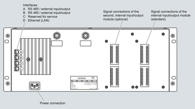
SIPROCESS UV600, gas connections and electrical connections
The SIPROCESS UV600 is supplied as standard with one or (optionally) two input/output modules. The logic function of the signal connections can be configured individually with the service and maintenance software specific to SIPROCESS UV600.
The signal connections are available at terminal strips X3, X4, X5 and X7 on the 12-pin plug connectors of the input/output modules. The scope of delivery includes the corresponding counterparts (plug connectors) with screw terminals.
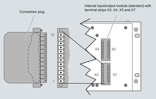
SIPROCESS UV600, signal connections and plug connectors
Pin assignments
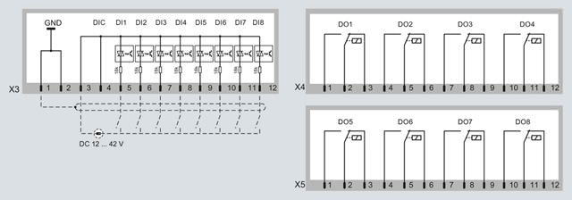
SIPROCESS UV600, pin assignments of digital inputs X3 (DI1 to DI8) and digital outputs X4 (DO1 to DO4) and X5 (DO5 to DO8)
Characteristics of the digital inputs:
- Floating optocouplers with common reference potential (DIC)
- Switching range 14 ... 42 V DC (external control voltage)
- The digital inputs can be operated either with positive or negative voltage
- With inverted switching logic, the logic function of the control input is active if no current is flowing through the control input
- Maximum voltage: ± 50 V
Characteristics of the digital outputs:
- Floating relay changeover contacts
- Single-pole changeover switch, three connections
- Maximum voltage: ± 50 V
- Connect inductive loads (e.g. relays, solenoid valves ...) via spark-quenching diodes only
- Maximum load-carrying capacity (standard): Max. 30 V AC, max. 48 V DC, max. 500 mA.
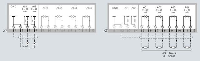
SIPROCESS UV600, pin assignment of the analog inputs X7 (AI1 and AI2) and analog outputs X7 (AO1 to AO4)
Characteristics of the analog inputs:
- The input signal is an analog current signal (standard 0 ... 20 mA, maximum 30 mA)
- The signal current must be provided by an external current source
- Load (internal resistance) of analog input: 10 Ω
- Reference potential GND (see figure, analog inputs)
- Overcurrent protection: ± 1 000 mA
- Max. voltage: ± 50 V
Characteristics of the analog outputs:
- Analog outputs are floating (electrically isolated) and provide a load-independent current signal
- Signal range 0 ... 24 mA
- Residual ripple 0.02 mA
- Resolution 0.1%
- Accuracy 0.25% of full-scale value
- Maximum load 500 Ω
- Maximum voltage ± 50 V
- Adjustable start or error state
Note for electrical isolation:
The electrical isolation is canceled if the negative poles of the analog outputs are connected to GND.
Технические данные
General information | |
Measuring ranges | 3, automatic measuring range switching |
Detection limit (2σ) | < 1% of span |
Smallest possible span | Dependent on order configuration |
Largest possible span | Dependent on order configuration |
UV lamp | |
| EDL, electrodeless discharge lamp |
| ≈ 2 years (17 500 h) |
Conformity | CE mark |
Design, enclosure | |
Degree of protection | IP40 |
Weight | approx. 17 kg |
Requirements of location of use | |
Installation location | Within closed building |
Atmospheric pressure in the environment | 700 …1 200 hPa |
Relative humidity | 10 ... 95%, non-condensing |
Permissible contamination | Pollution degree 1 |
Maximum geographic altitude of location of use | 2 500 m above sea level |
Permissible ambient temperature | |
| +5 ... +45 °C (41 ... 113 °F) |
| -10 ... +70 °C (14 ... 158 °F) |
Operating position | Front wall, vertical |
Permissible vibration/shock | |
| 0.035 mm (in the range 5 ... 59 Hz) |
| 5 m/s2 (in the range 59 … 160 Hz) |
Electrical characteristics | |
Line voltage (optional, see nameplate) | 93 ... 132 V AC, 186 ... 264 V AC |
Line frequency (AC) | 47 ... 63 Hz |
Permissible overvoltages (transient surges in the power supply network) | Up to overvoltage category II in accordance with IEC 60364-4-443 |
Power consumption | Approx. 50 VA, max. 300 VA |
EMC interference immunity (electromagnetic compatibility) | In accordance with EN 61326-1, EN 61326-2-1, EN 61000-6-2, EN 61000-6-4 and EU Directive 2004/108/EC. In the case of electromagnetic radiation in the frequency range from 750 MHz ± 20 MHz, increased measuring errors can occur for small measuring ranges |
Electrical safety | In accordance with EN 61010-1 |
Internal line fuses | |
| 6.3 A, not replaceable |
| 8 A |
Gas inlet conditions | |
Permissible sample gas pressure | Relative to ambient/atmospheric air pressure: -200 ... +300 hPa (-0.2 ... +0.3 bar) |
Sample gas flow | 20 ... 120 l/h (333 ... 2 000 ml/min) |
Sample gas temperature | 5 ... 55 °C |
Measuring response | |
(relating to sample gas pressure 1 013 hPa absolute, 0.5 l/min sample gas flow and 25 °C ambient temperature) | |
Reference point drift | < ±1%/week of respective span |
Zero point drift | |
| < ± 1%/week of respective span |
| < ± 2%/week of respective span |
| < ±1%/day of respective span |
Repeatability (reproducibility) | < ± 1% of respective span |
Linearity error | < ± 1% of respective span |
Electric inputs and outputs | |
Analog output | 4, 0 ... 24 mA; floating (electrically isolated), residual ripple 0.02 mA, resolution 0.1% (20 μA), max. load 500 Ω, max. voltage ± 50 V |
Relay outputs | 8, with changeover contacts, max. voltage ± 50 V loading capacity: Max. 30 V AC / max. 48 V DC / max. 500 mA |
Analog inputs | 2, 0 ... 20 mA, reference potential GND, signal strength max. 30 mA, overcurrent protection max. ± 1 A, voltage max. ± 50 V |
Digital inputs | 8, switching range 14 ... 42 V (external control voltage), max. voltage ± 50 V |
Serial interface | RS485, Ethernet (LAN) |
1) Only for daily recalibration and air-conditioned environment ( +/- 2 °C)


 Ответ от производителя может занять до 5 дней и более.

