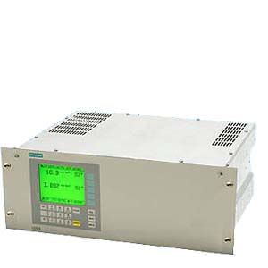
19 central unit Siemens
Чертеж

LDS 6, 19" central unit, dimensions in mm
Схема подключения
Pin assignments

LDS 6, 19" central unit, pin assignments
Optical and electrical connections

LDS 6, three-channel 19" central unit, optical and electrical connections
Технические данные
LDS 6, 19" central unit | |
Analytical performance | |
Measuring range | Depending on sample gas component: See table for standard applications. |
Detection limit (DL): Calculated in accordance with VDI 2449, measured on every supplied analyzer during the temperature test (between 5 ... 45 °C) in accordance with VDI 4203. | Depending on sample gas component: see table for standard applications. For application letter ET and FT: in accordance with the requirements of 17th and 27th BImSchV |
Smallest recommended measuring range (with 1 m path length) | Depending on sample gas component: see table for standard applications. |
The maximum applicable measuring ranges can be found in the table of standard combinations. These can only be applied if the individual process conditions allow it. Please contact the Technical Support from Siemens for checking the applicability. | |
Accuracy1) | 2% / 5%, depending on sample gas component and application letter. At best: detection limit. See table for standard applications. For application letter ET and FT: in accordance with the requirements of 17th and 27th BImSchV |
Linearity | Better than 1% |
Repeatability | 2% of the measured value or same amount as the detection limit (whichever is larger) For application letter ET and FT: in accordance with the requirements of 17th and 27th BImSchV |
Calibration interval | No recalibration required thanks to internal reference cell |
General information | |
Concentration units | ppmv, Vol%, mg/Nm3 |
Display | Digital concentration display (5 digits with floating decimal point) |
Laser protection class | Class 1, safe to the eye |
Certificates | CE marking, TÜV, MCERTS |
Design, enclosure | |
Degree of protection | IP20 according to EN 60529 |
Dimensions | 177 x 440 x 380 mm |
Weight | Approx. 13 kg |
Mounting | Horizontal |
Electrical characteristics | |
Power supply | 100 ... 240 V AC 50 ... 60 Hz, automatically adapted by the system; with a 3-channel central unit, an additional external power supply +24 V DC, 50 VA is included in the scope of delivery |
Power consumption | 50 W |
EMC | According to EN 61326 and standard classification of NAMUR NE21 |
Electrical safety | According to EN 61010-1, overvoltage classification II |
Fuse specifications | 100 ... 240 V: T2.5L250V |
Time response | |
Warm-up time at 20 °C ambient temperature | Approx. 15 min |
Response time | Min. of 1 s, depending on application |
Integration time | 1 … 100 s, adjustable |
Influencing variables | |
Ambient temperature | < 0.5%/10 K of the measured value |
Atmospheric pressure | Negligible |
Process gas pressure compensation | Recommended |
Process gas temperature compensation | Recommended |
Process gas pressure range | See table for standard applications |
Power supply changes | < 1%/30 V |
Electrical inputs and outputs | |
Number of measurement channels | 1 … 3, optional |
Analog output | 2 per channel, 4 ... 20 mA, floating, ohmic resistance max. 750 Ω |
Analog inputs | 2 per channel, designed for 4 ... 20 mA, 50 Ω |
Binary outputs | 6 per channel, with changeover contacts, configurable, 24 V AC/DC/1 A, floating |
Binary inputs | 6 per channel, designed for 24 V, floating, configurable |
Communication interface | Ethernet 10BaseT (RJ-45) |
Climatic conditions | |
Temperature range | 5 … 45 °C during operation, -40 … +70 °C during storage and transportation |
Atmospheric pressure | 800 … 1 200 hPa |
Humidity | < 85% relative humidity, above dew point (in operation and storage) |
1) The accuracy corresponds to intrinsic uncertainty according to IEC 61207 for 7MB6121-xKD00-0xxx
Дальнейшая информация
The following table lists the measuring conditions for standard applications. The listed values for the measuring range and detection limit (DL) are only approximate values. The exact values at the respective measuring point depend on the totality of all influencing variables and can be determined by Siemens for the specific case. Please note that the values for the detection limit and the maximum measuring range refer to a path length of 1 m. Longer path lengths will improve the detection limit, but not linearly. This is due to limiting effects such as dust load. The maximum applicable measuring ranges can only be used if permitted by the process conditions such as dust load.
Standard application Effective optical path length: 0.3 … 12 m Dust load2): < 50 g/Nm3 | Process gas temperature Tmin … Tmax | Process gas pressure pmin … pmax | Min. measuring range (with 1 m eff. opt. path length) | Max. measuring range (also dependent on eff. opt. path length: see following column) | (Max. measuring range x path length) | (DL x path length) | Accuracy3) | ||||
|---|---|---|---|---|---|---|---|---|---|---|---|
under standard conditions1) without cross-interferences of other gases | At 1 013 hPa with cross-interference of gas 2 | ||||||||||
Gas 1 | Gas 2 | Gas code | Appl. code | Gas 1 | Gas 1 | Gas 1 | Gas 1 | Gas 1 | Gas 1 | ||
O2 | A | B6) | 600 … 1 200 °C | 950 …1 050 hPa | 0 … 15 vol% | 0 … 100 vol% | 240 vol%*m | 0.3 vol%*m | 5% | ||
C | 0 … 600 °C | 950 …1 050 hPa | 0 … 5 vol% | 0 … 100 vol% | 75 vol%*m | 0.1 vol%*m | 2%4) | ||||
P | 0 … 200 °C | 950 … 5 000 hPa | 0 … 5 vol% | 0 … 100 vol% | 75 vol%*m | 0.1 vol%*m | 2% | ||||
NH3 | C | A | 0 … 150 °C | 950 … 1 050 hPa | 0 … 25 ppmv | 0 … 500 ppmv | 2 500 ppmv*m | 0.5 ppmv*m | 0.9 ppmv*m At 15 vol% H2O, 55 °C | 2% | |
T | 0 … 150 °C | 950 … 1 050 hPa | 0 … 25 ppmv | 0 … 500 ppmv | 2 500 ppmv*m | 0.5 ppmv*m | 0.9 ppmv*m At 15 vol% H2O, 55 °C | 2% | |||
E | 250 … 350 °C | 950 … 1 050 hPa | 0 … 45 ppmv | 0 … 500 ppmv | 2 500 ppmv*m | 0.9 ppmv*m At 250 °C | 1.4 ppmv*m At 15 vol% H2O, 250 °C | 2% | |||
F | 300 … 400 °C | 950 … 1 050 hPa | 0 … 50 ppmv | 0 … 500 ppmv | 2 500 ppmv*m | 1 ppmv*m At 300 °C | 1.5 ppmv*m At 15 vol% H2O, 300 °C | 2% | |||
L7) | 0 … 400 °C8) | 920 … 1 120 hPa | 0 … 15 ppmv | 0 … 500 ppmv | 2 500 ppmv*m | 0.5 ppmv*m | 1.4 ppmv*m At 15 vol% H2O, 250 °C | 2 % | |||
NH3 | H2O | D | A | 0 … 150 °C | 950 … 1 050 hPa | 0 … 25 ppmv | 0 … 100 ppmv | 1 200 ppmv*m | 0.5 ppmv*m | 0.9 ppmv*m At 15 vol% H2O, 55 °C | 2% |
T | 0 … 150 °C | 950 … 1 050 hPa | 0 … 25 ppmv | 0 … 100 ppmv | 1 200 ppmv*m | 0.5 ppmv*m | 0.9 ppmv*m At 15 vol% H2O, 55 °C | 2% | |||
E | 250 … 350 °C | 950 … 1 050 hPa | 0 … 45 ppmv | 0 … 100 ppmv | 1 200 ppmv*m | 0.9 ppmv*m At 250 °C | 1.4 ppmv*m At 15 vol% H2O, 250 °C | 2% | |||
F | 300 … 400 °C | 950 … 1 050 hPa | 0 … 50 ppmv | 0 … 100 ppmv | 1 200 ppmv*m | 1 ppmv*m At 300 °C | 1.5 ppmv*m At 15 vol% H2O, 300 °C | 2% | |||
L7) | 0 … 400 °C8) | 920 … 1 120 hPa | 0 … 15 ppmv | 0 … 100 ppmv | 1 200 ppmv*m | 0.5 ppmv*m | 1.4 ppmv*m At 15 vol% H2O, 250 °C | 2 % | |||
HCl | E | A | 0 … 150 °C | 950 … 1 050 hPa | 0 … 30 ppmv | 0 … 6 000 ppmv | 1 200 ppmv*m | 0.6 ppmv*m | 2.2 ppmv*m At 15% H2O, 55 °C | 5% | |
T | 120 … 210 °C | 950 … 1 050 hPa | 0 … 10 ppmv | 0 … 60 ppmv | 720 ppmv*m | ||||||
H | 150 … 250 °C | 950 … 1 050 hPa | 0 … 50 ppmv | 0 … 6 000 ppmv | 1 200 ppmv*m | 1.0 ppmv*m At 150 °C | 3.1 ppmv*m At 15 vol% H2O, 150 °C | 5% | |||
HCl | H2O | F | A | 0 … 150 °C | 950 … 1 050 hPa | 0 … 30 ppmv | 0 … 100 ppmv | 1 200 ppmv*m | 0.6 ppmv*m | 2.2 ppmv*m At 15% H2O, 55 °C | 5% |
T | 120 … 210 °C | 950 … 1 050 hPa | 0 … 10 ppmv | 0 … 60 ppmv | 720 ppmv*m | ||||||
H | 150 … 250 °C | 950 … 1 050 hPa | 0 … 50 ppmv | 0 … 100 ppmv | 1 200 ppmv*m | 1.0 ppmv*m At 150 °C | 3.1 ppmv*m At 15 vol% H2O, 150 °C | 5% | |||
HF | G | A | 0 … 150 °C | 950 … 1 050 hPa | 0 … 5 ppmv | 0 … 1 500 ppmv | 200 ppmv*m | 0.1 ppmv*m | 0.6 ppmv*m At 15 vol% H2O, 55 °C | 5% | |
H | 150 … 250 °C | 950 … 1 050 hPa | 0 … 5 ppmv | 0 … 1 500 ppmv | 200 ppmv*m | 0.11 ppmv*m At 150 °C | 0.6 ppmv*m At 15 vol% H2O, 150 °C | 5% | |||
HF | H2O | H | A | 0 … 150 °C | 950 … 1 050 hPa | 0 … 5 ppmv | 0 … 200 ppmv | 200 ppmv*m | 0.1 ppmv*m | 0.6 ppmv*m At 15 vol% H2O, 55 °C | 5% |
H | 150 … 250 °C | 950 … 1 050 hPa | 0 … 5 ppmv | 0 … 200 ppmv | 200 ppmv*m | 0.11 ppmv*m At 150 °C | 0.6 ppmv*m At 15 vol% H2O, 150 °C | 5% | |||
CO | J | C | 0 … 600 °C | 950 … 1 050 hPa | 0 … 1.5 vol% | 0 … 100 vol% | 40 vol%*m | 300 ppmv*m | 1 500 ppmv*m at 50 vol% CO2, 20°C | 2% | |
CO | CO2 | K | D | 0 … 400 °C | 800 …1 400 hPa | 0 … 5 vol% | 0 … 100 vol% | 0 ... 200 vol%*m | 0.1 vol%*m | 0.5 Vol% at 50 vol% CO2, 20°C | 2%5) |
CO2 | L | A | 0 … 150 °C | 950 … 1 050 hPa | 0 … 7.5 vol% | 0 … 100 vol% | 40 vol%*m | 300 ppmv*m | 2% | ||
H2O | M | A | 0 … 150 °C | 950 … 1 050 hPa | 0 … 5 vol% | 0 … 30 vol% | 240 vol%*m | 0.1 vol%*m | 5% | ||
T | 0 … 150 °C | 950 … 1 050 hPa | 0 … 5 vol% | 0 … 30 vol% | 240 vol%*m | 0.1 vol%*m | 5% | ||||
1) All technical specifications apply to an optical path distance of 1 m in a nitrogen atmosphere under standard conditions 25 °C (or Tmin) and 1013 hPa. The effective detection limit, the measuring range and the accuracy can be influenced by process parameters such as pressure, temperature and gas composition. Not all combinations of maximum pressure and temperature can be realized with the minimum measuring ranges. If the process conditions deviate from the specifications of the standard applications, special applications are also possible on request. Complete the application questionnaire which can be found on the Internet at www.siemens.de/insitufragebogen.
2) At 0.3 m effective optical path length, average diameter of the dust particles: 15 µm, specific weight of the dust particles: 650 kg/m3
3) At least: Detection limit
4) Up to 200 °C, 5% above this
5) The accuracy corresponds to intrinsic uncertainty according to IEC 61207: 2 % of MV (0 ... 200°C); 2.5 % of MV (0 ... 400°C); at best 0.25 vol%*m.
6) At high process temperatures, the use of an IR filter A5E00534668 is recommended for the CD 6 sensor (see page 2/xx).
7) Suitable for use to measure NH3 according to the requirements of Directive 295/2009/EC "Implementing regulations on type-approval of motor vehicles and engines with respect to emissions from heavy duty vehicles (EURO VI)" from 18 June 2009 and its regulation for implementation of number 582/2011/EC from 25 May 2011 of the Commission of the European Union.
8) The device is also able to operate above 400 °C to 1 000 °C. Due to the decomposition of NH3 at higher temperatures, no specification can be given in these ranges.
Standard application Effective optical path length: 0.3 … 12 m Dust load3): < 50 g/Nm3 | Min. measuring range (with 1 m eff. opt. path length) | Max. measuring range (usually also dependent on eff. opt. path length: see following column) | (Max. measuring range x path length) | (DL x path length) | Accuracy4) | Purging gas mode | Purging gas medium | |||||
|---|---|---|---|---|---|---|---|---|---|---|---|---|
under standard conditions1) 2) | At 1 013 hPa with cross-interference of gas 1 | |||||||||||
Gas 1 | Gas 2 | Gas code | Appl. code | Gas 2 | Gas 2 | Gas 2 | Gas 2 | Gas 2 | Gas 2 | Standard | Optional | |
O2 | A | B6) | E, F | G, H | Steam + air, N2 | |||||||
C | D | B | N2 | |||||||||
P | D | B | N2 | |||||||||
NH3 | C | A | C | G | Air | |||||||
T | C | G | Air | |||||||||
E | E | G | Air | |||||||||
F | E | G | Air | |||||||||
L | C | D | Air | |||||||||
NH3 | H2O | D | A | 0 … 5 vol% | 0 … 30 vol% | 240 vol%*m | 0.1 vol%*m | 0.1 vol%*m | 5% | C | G | Air |
T | 0 … 5 vol% | 0 … 30 vol% | 240 vol%*m | 0.1 vol%*m | 0.1 vol%*m | 5% | C | G | Air | |||
E | 0 … 5 vol% | 0 … 30 vol% | 240 vol%*m | 0.1 vol%*m At 250 °C | 0.1 vol%*m At 250 °C | 5% | E | G | Air | |||
F | 0 … 5 vol% | 0 … 30 vol% | 240 vol%*m | 0.1 vol%*m at 300 °C | 0.1 vol%*m at 300 °C | 5% | E | G | Air | |||
L | 0 … 5 vol% | 0 … 30 vol% | 250 vol%*m | 0.1 vol%*m at 250 °C | 0.1 vol%*m at 250 °C | 5 % | C | D | Air | |||
HCl | E | A | C | G | Air | |||||||
T | C | G | Air | |||||||||
H | E | G | Air | |||||||||
HCl | H2O | F | A | 0 … 5 vol% | 0 … 30 vol% | 360 vol%*m | 0.1 vol%*m | 0.1 vol%*m | 5% | C | G | Air |
T | 0 … 5 vol% | 0 … 30 vol% | 360 vol%*m | C | G | Air | ||||||
H | 0 … 5 vol% | 0 … 30 vol% | 360 vol%*m | 0.1 vol%*m At 150 °C | 0.1 vol%*m At 150 °C | 5% | E | G | Air | |||
HF | G | A | C | G | Air | |||||||
H | E | G | Air | |||||||||
HF | H2O | H | A | 0 … 5 vol% | 0 … 30 vol% | 360 vol%*m | 0.1 vol%*m | 0.1 vol%*m | 5% | C | G | Air |
H | 0 … 5 vol% | 0 … 30 vol% | 360 vol%*m | 300 ppmv*m At 200 °C | 300 ppmv*m At 200 °C | 5% | E | G | Air | |||
CO | J | C | E | G | Air, N2 | |||||||
CO | CO2 | K | D | 0 … 10 vol% | 0 … 100 vol% | 0 ... 200 vol%*m | 0.2 vol%*m | 1 vol% at 50 vol% CO, 20°C | 5%5) | C | G | Air |
CO2 | L | A | C | G | Air | |||||||
H2O | M | A | C | G | Air | |||||||
T | C | G | Air | |||||||||
1) At 20 °C, 1 013 hPa
2) If the smallest permissible process gas temperature of the application is Tmin > 20 °C, the detection limit refers to Tmin and standard pressure (1 013 hPa)
3) At 0.3 m optical path length, average diameter of the dust particles: 15 µm, specific weight of the dust particles: 650 kg/m3
4) At least: Detection limit
5) The accuracy corresponds to intrinsic uncertainty according to IEC 61207: 5% of MV; at best 0.5 vol%*m.
6) At high process temperatures, the use of an IR filter A5E00534668 is recommended for the CD 6 sensor (see page 2/xx).
Special applications
 | If the process conditions deviate from the specifications of the standard applications, special applications are also possible on request. Please complete the application questionnaire which can be found on the Internet at www.siemens.de/insitufragebogen. |


 Ответ от производителя может занять до 5 дней и более.

