MAXUM edition II Siemens

Область применения
Chemical industry
- Monitoring of benzene in styrene in the ppb range
- Traces of residual gases in ultra-pure gases
- Determination of traces of hydrocarbons in air separation plants
- Fast analysis of CS2 and H2S in seconds
- Fast measurement of C6 to C8 aromatic compounds including the measurement of C9+ aromatics
- Monitoring of hydrogen in chlor-alkali plants
- Measurement of sulfurous components
- Measurement of C9 to C18 paraffins
- Determination of vinyl chloride in room air in a 60-second cycle
- Gas analysis during manufacture of vinyl chloride monomer (VCM)
Oil & gas
- Crack gas analysis
- Natural gas: Trace analysis for components such as mercaptans, H2S or COS
- Fast determination of benzene in naphtha
- Determination of high boiling aromatics in a distillation fraction
- Fast measurement of acetylene in ethylene
- Total sulfur in petrol and diesel
Water/waste water
- Determination of halogenated hydrocarbons
- Simultaneous determination of chlorinated hydrocarbons, aromatics and alcohols in water
- Wastewater monitoring with PGC and stripper
Power engineering
- Power generation in coal-fired power plant.
Automotive industry
- Fast analytical measurement of methane in car exhausts
- High-speed chromatography for small molecules in propellants
Обзор
The MAXUM edition II is a universal process gas chromatograph for flexible process applications with a wide variety of analytical possibilities. The MAXUM edition II combines various functional modules with a flexible oven concept and can therefore also optimally solve complex applications.
The MAXUM edition II is used in all sectors of the chemical industry, petrochemicals and refineries. It analyzes the chemical composition of gases and liquids in all production phases. The MAXUM edition II is suitable for installation in an analysis cabinet close to the process or in a close laboratory. Thanks to the flexible application possibilities, it can be used to analyze the initial material, the end product and also secondary products. The MAXUM edition II can also be used for many applications with environmental measurements.
The MAXUM edition II has extremely rugged and specially designed hardware and software. It automatically takes a sample from the process, and injects this onto the chromatographic columns.
With its powerful software and hardware, it satisfies the highest demands for measurement repeatability, and can be operated for a long time without manual interventions. Using powerful communications tools, the MAXUM edition II can send its results to process control systems. The comprehensive networking facilities can be applied to use several MAXUM edition II chromatographs together in large networks.
Дизайн
Chromatographic measuring equipment consists of a sampling system matched to the application, sample preparation with switchover to various sample streams if necessary, and the gas chromatograph with the analytical and electronic hardware as well as data processing, operation and communications software.
The MAXUM edition II gas chromatograph is divided into three sections depending on the version:
- The upper section contains the electronics with the power supply, controllers and analog electronics
- The middle section contains the pneumatics and some of the detectors (not with MAXUM edition II modular oven version)
- The bottom section contains the oven and the complete analytical components responsible for the separation
The MAXUM edition II is available prepared for wall mounting or for free mounting on a rack.
Extension of functionality
Network Access Unit (NAU)
- A MAXUM edition II without analytical section
- Available with or without HMI
- Has 7 slots for optional I/O plug-in cards
- Offers central MODBUS connection of several chromatographs to the control system
Функции
Supply with carrier gas, combustion gas and auxiliary gases
A gas chromatograph must be supplied with carrier gas and, if applicable, combustion gas and other auxiliary gases depending on the analytical configuration. The carrier gas is used to transport the sample through the analytical system. Auxiliary gases are used to operate valves, as combustion gases for flame ionization detectors, and to purge the oven.
Injection system
The injection system is the link between the continuous process stream and the discrete analytical process. It is responsible for injecting an exactly defined portion of the sample in a reproducible and pulsed manner (as far as possible) into the carrier gas stream.
The injection can be carried out in the conventional manner using valves or by means of a live injection:
- Gaseous samples (0.1 to 5 ml)
- Completely vaporizable liquid samples (0.1 to 10 µl)
Gas injection valves
Model 50 10-port valve:
- Combined gas injection and backflushing valve
- Activation by pressure on the diaphragm without moving parts
- Can be used as gas injection valve or for column switching (6-port connection)
- > 3 million switching cycles without maintenance
Model 11 6-port valve:
- Can be used as gas injection valve, liquid injection valve or for column switching
- Diaphragm controlled by tappet
- One million switching cycles without maintenance
Liquid injection valve FDV
A constant quantity of a liquid sample can be automatically injected using the liquid injection valve, and subsequently vaporized rapidly and completely. The valve can also be used to inject small volumes of gas.
The liquid injection valve consists of three sections:
- Thermostatically-controlled vaporization system
- Sample passage section with seal
- Pneumatic drive
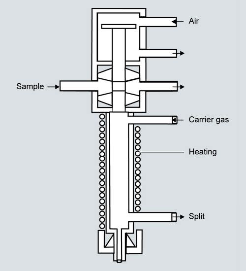
Liquid injection valve FDV
Features:
- Vaporization temperature 60 to 350 °C
- Injection volume 0.1 to 9.5 μl
- Sample temperature -20 to +150 °C
- Material of parts wetted by sample: Stainless steel, mat. no. 1.4571, Hastelloy, Monel or special materials
- Control pressure 400 to 600 hPa
- Max. sample pressure 6 000 kPa, recommended 50 to 100 kPa
- Connections for pipe: 3.14 mm (1/8") outer diameter
Live injection add-on part
Flexible selection of the injection volume which is exactly matched to the analytical tasks and the requirements of the columns is possible with the live injection add-on part.
Live injection
Oven
A further important factor for the separating performance is the temperature This has a very high influence on the vapor pressure of the individual components, and thus on the diffusion and the distribution equilibrium between the mobile and stationary phases in the column. This influences the retention times, and thus the identification of components. Therefore very high demands are placed on the temperature stability and repeatability of the oven and also on that of the injection equipment and the detectors.
Two different types of oven are available:
Airless oven for extremely stable isothermal oven temperatures (0.02 °C control accuracy) up to 80 °C (modular oven) or 280 °C depending on the version.
Airbath oven for
- isothermal (5 to 225 °C) or
- temperature-programmed mode
Both types of oven are available as
- single ovens or
- dual ovens.
With the dual ovens, two separate heating circuits provide independent oven temperatures. It is then possible to use two different temperatures for the respectively installed columns for one application or to carry out two or more applications in one chromatograph with different temperatures for the separation.
In order to measure sample components with highly different volatilities, a temperature program is frequently used for the chromatographic separation. In this case the column temperature is continuously increased according to a selectable heating-up rate. This method (PTGC) is available with the MAXUM edition II.
The internal oven consists of a chamber with low thermal capacity located within the standard oven. It contains the capillary column used for the separation.
The ovens have separate, independent temperature control. The temperature of the internal oven is freely-programmable. The temperature changes according to the time-dependent profile assigned to the respective analysis. Up to three linear ramps and four constant periods can be configured.
It is then possible to determine components with low and high boiling points in one analysis. Existing laboratory applications can be opened up by PTGC for use in the process industry.
"Simulated distillation" is an important application of PTGC in refineries. The distillation range - a quality criterion for fuels - is chromatographically traced "online".
Columns
The columns are the central component of the chromatograph. They resolve the gas mixture or the vaporized liquid into its individual components. The following distinction is made:
- Packed/micropacked columns with inner diameter of 0.75 to 3 mm
- Capillary columns with inner diameter of 0.15 to 0.53 mm
Packed columns are mechanically stable and simple to handle. Capillary columns have a significantly higher separating performance, often with a shorter analysis period and lower analysis temperature.

Types of column
Column switching systems
Process chromatographs are almost always equipped with column switching functions. Column switching is understood to be the combination of several columns in the carrier gas path which are arranged in succession or parallel. These columns usually have different separating performances, and are interconnected by valves for switching over the gas path. A distinction is made between backflushing, cut and distribution.
A wide range of techniques is available for column switching.
The techniques comprise highly stable membrane gas valves, membrane piston valves, sliding vane rotary valves and also valveless switching techniques.
Valves
Model 50 10-port valve:
- Combined gas injection and backflushing valve
- Activation by pressure on the diaphragm without moving parts
- Switches gas samples at an overpressure of 0 to 500 kPa
- Can be used as gas injection valve or for column switching (6-port connection)
- > 3 million switching cycles without maintenance
Model 11 6-port valve:
- Can be used as gas injection valve, liquid injection valve or for column switching
- Diaphragm controlled by tappet
- One million switching cycles without maintenance
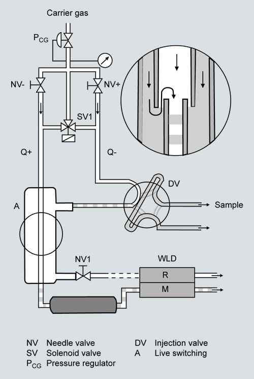
Valveless switching technique
The valveless live column switching is exactly controlled by electronic pressure regulators, and prevents falsification of results since the sample does not come into contact with valves. A special pressure-controlled coupling element connects the capillary columns.
This technique is optimally suitable for capillary columns, and offers the best long-term stability and reliability. Live column switching is a technique where backflushing, cut or distribution is carried out on two different columns without any switching of valves or other moving components in the separation path.
This is achieved using a unique coupling unit, the live T-piece. Its function is based on pressure difference control regulated by the electronic precision pressure controllers of the MAXUM edition II. Because there is no dead volume whatsoever, it is ideally suitable for the low flow rates used with capillary columns. Maintenance of the column switching configuration is then superfluous, the separating performance is improved, and complicated separating procedures are simplified.
Live switching

Live switching
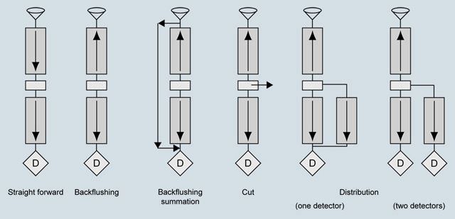
Column switching systems (examples)
Solenoid valve control module
- Contains all control elements in one module in order to reduce downtimes during repairs to a minimum
- Has 3-way and 4-way distributors for control of many different types of valve
- Uses separate, plug-on pipe connectors to permit implementation of variable gas supplies
Electronic pressure controller module (EPC)
- Permits exact control of pressure without mechanical pressure regulator. Shortens the setup time since the pressure is set by an operator input.
- Permits programmable pressure changes for fast chromatography and modern applications.
- Controls the supply of carrier gas and combustion gas Avoids drift and deviations which can occur with mechanical pressure control.
Detectors
Thermal conductivity detectors (TCD) and flame ionization detectors (FID) are mainly used in process chromatography. Specific detectors such as flame photometer detector (FPD), electron capture detector (ECD), photo-ionization detector (PID), or helium ionization detector (HID) are used to a lesser extent.
The detector modules described above can be combined together in many different manners in the MAXUM edition II.
- A maximum of three detector modules can be used in the airbath oven.
- Up to three modules (depending on the type) can be used in the airless oven, the dual airless oven and the ovens with temperature programming.
- Thermal conductivity detectors (TCD) are used in the modular oven system.
- In the case of multiple modules such as the TCD, the measuring cells can be operated in parallel at offset times in order e.g. to increase the number of analyses within a specific time.
- Multiple modules can each be used with a column system for one sample stream. This shortens the total cycle time with multi-stream applications.
- Parallel use of two identical column systems provides redundant measurements which can be compared with each other, thus reducing the necessity for calibration.
Detector | Measured value dependent on: | Selectivity | Application example |
|---|---|---|---|
 | Concentration | Universal | Main and subsidiary components |
 | Mass flow | Thermally ionizable components at < 1 000 °C | Hydrocarbons |
 | Mass flow | Substances containing S or P | Traces of sulfur in HC matrices |
 | Mass flow | Universal (except He and Ne) | Ultra-pure gas analysis |
 | Mass flow | Molecules with electronegative groups | Traces of halogenated hydrocarbons |
 | Mass flow | Selective, dependent on ionization potential | Traces of aromatic compounds, amines |
Suitable detectors for process gas chromatography
Thermal conductivity detectors (TCD)
The measuring principle of the TCD is based on the difference between the thermal conductivity of a pure carrier gas stream and that of a gas mixture containing carrier gas and a component eluted from the column. Therefore all components whose thermal conductivity differs from that of the pure carrier gas can be detected by a TCD.
TCDs always consist of one to three measuring cells and one or two reference cells which are electrically heated and contain wire resistors or thermistors connected in a Wheatstone bridge.
The amount of heat transferred to the cells is the same as long as pure carrier gas flows through the measuring and reference cells. The resistances are therefore also very similar, and the bridge resistors are balanced. If a mixture of carrier gas and sample component flows through the sample chamber, the change in thermal conductivity of the gas mixture also changes the amount of heat transferred and thus the temperature and resistance of the heating wires or thermistors in the sample chamber.
The resulting offset in the bridge circuit is directly proportional to the current concentration of the sample component in the carrier gas stream.
Versions of TCDs:
- Thermistor detector
- Filament detector
Both detectors are available for universal use, and the filament detector can also be used at higher temperatures. The thermistor detector is available as a block with 6 measuring detectors and two reference detectors. The filament detector has a measuring cell and a reference cell.
Flame ionization detector (FID)
With the flame ionization detector (FID), the gas leaving the column is burnt in a constantly burning hydrogen flame. If this gas mixture contains thermally ionizable components, e.g. flammable organic compounds, ions are generated when the compounds are burnt. These ions can transport charges which change (increase) the conductivity of the gas in the vicinity of the flame. In order to measure the conductivity or the number of ions, these can be collected at an electrode.
An electrode voltage is applied between the nozzle from which the flame burns and the electron collector positioned above it.
The resulting current is amplified, and is the measured signal.
In contrast to the TCD (concentration-dependent signal), the signal with the FID is proportional to the mass flow of the components.
The FID features a linear range of 6 to 7 powers of ten, and permits detection limits of less than 0.1 ppm (referred e.g. to the concentration of the hydrocarbon in the sample). Non-flammable components or those which only thermally ionize with difficulty (e.g. inert gases and water), or components which do not indicate thermal ionization at approx. 1 700°C, cannot be measured with the FID.
In addition to the carrier gas, hydrogen and air are required as the flame gases to operate this detector.
Flame photometer detector (FPD)
Further detector principles are used for determination of trace concentrations of specific components. For example, the flame photometer detector is used to determine traces of compounds containing sulfur or phosphor. The emission of light of characteristic wavelengths is measured when burning the substances in a reducing hydrogen flame.
Pulsed discharge detector (PDD)
The detector can be used in three different versions: HID (helium ionization detector), ECD (electron capture detector) and PID (photo ionization detector). Installation in the Maxum GC is possible without further modification, and the detector can only be used in non-hazardous areas. The PDD uses stable, pulsed DC discharges in helium as the ionization source. The detector''s performance data is equal to or better than that of detectors which use radioactive ionization sources. Since a radioactive source is not used, the complex directives for radiation protection need not be observed by the customer.
- PDHID (helium ionization detector)
The PDHID works almost destruction-free with an ionization rate of 0.01 to 0.1%, and has a high sensitivity. The sensitivity for organic components is linear over five orders of magnitude, and the detection limit is in the low ppb range. The PDHID can be used universally for organic and inorganic components, with the exception of helium and neon. - PDECD (electron capture detector)
In electron capture mode, sample components with a high electron affinity can be selectively detected, such as halogenated hydrocarbons. The detector''s properties and sensitivity are comparable with those of a 63Ni ECD. It is necessary to use a supplementary gas in this mode (recommended: 3% xenon in helium). - PDPID (photo ionization detector)
A supplementary gas must also be used in this mode. Addition of 1-3 vol% of argon, krypton or xenon to the auxiliary gas leads to kinetic excitation of the added gas. The detector is used in this configuration for selective detection of aliphatic compounds, aromatic compounds and amines. The selectivity or energy level can be determined through the choice of added gas. The sensitivity in this mode is limited to sample components whose ionization potential is below the kinetic emission energy of the added gas.
Accessories: Catalytic air purifier
Instrument air is usually contaminated by traces of hydrocarbons. If this air is used as the combustion gas for a flame ionization detector (FID), the impurities are evident as disturbing background noise.
The catalytic air purifier eliminates interfering impurities of hydrocarbons in the combustion air for the FID detector. The products of the catalytic oxidation (H2O, CO2) have no influence on the detector. Use of the catalytic air purifier significantly reduces the background noise. It has a flameproof housing and is therefore explosion-proof.
The air within the purifier is passed through a spiral lined with palladium. This metal spiral is heated up to approx. 600 °C. Palladium has a high activity at this temperature, and almost complete catalytic oxidation is achieved despite the short dwell time. The air subsequently passes through a cooling loop, and is output purified and cooled.
Parallel chromatography
This function divides a complex application into several simple sub-applications which are analyzed in parallel. This reduces the cycle times.
The hardware and software of the MAXUM edition II allows a complex chromatographic analysis to be divided into several simple analyses. Each of these simple analyses can then be simultaneously executed in parallel. This not only simplifies the complete analysis, it can also be carried out faster and with greater reliability. In addition, maintenance of the simplified analyses is easier and faster.
State-of-the-art communication
TCP/IP communication and standard Ethernet hardware mean that MAXUM edition II is compatible with many networks.
Software
For simple operation and maintenance, MAXUM edition II offers an online software system with local operation over an HMI and a flexible GUI accessible using a computer workstation.
The online software system is installed in every MAXUM edition II or NAU and includes:
- Embedded EZChrom evaluation
- Embedded MaxBasic in the runtime version
- Communications software, network software, I/O driver in order to operate the gas chromatograph
The PC Workstation Software Gas Chromatograph Portal comprises:
- MAXUM edition II workstation tools:
- NetworkView to provide an overview of the network
- Method builder
- MMI maintenance panel emulator
- Data logger
- Modbus utility
- Backup and restore utilities
- Online system download utilities
- Online help and documentation
and optional packages for individual ordering, e.g.:
- MaxBasic editor
- Simulated distillation method
- OPC communications server
Compatibility
MAXUM edition II is compatible with all older types of chromatograph from Siemens: Advance Maxum.
Application
Certain parameters must be observed during application and subsequent operation of the MAXUM edition II. It can then be determined qualitatively whether the task is fulfilled. The basic prerequisite for this is that all components can be detected and clearly isolated from the interfering components. Important parameters are: Analysis period, measuring ranges, detection limits and repeatability of the results.
Чертеж

Notes: Only for airbath oven:
Left outlet for applications with one single oven
Left and right outlets for applications with divided oven
MAXUM edition II, dimensions in mm
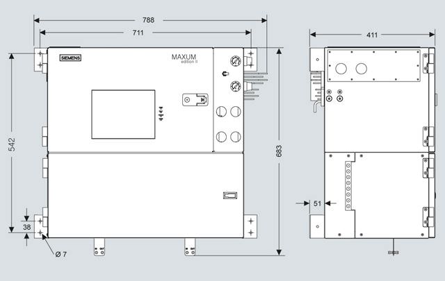
MAXUM edition II modular oven, dimensions in mm
Особенности
MAXUM edition II with its combination of different analytical components offers a wide range of analytical possibilities. It is therefore possible to solve highly different measuring tasks with just one product. This reduces the costs for investment, training and stocking of spare parts.
The MAXUM edition II platform offers:
- Numerous oven configurations permit an optimum solution for almost every application
- Numerous types of detector and valve for the optimum analytical solution
- Intelligent electronics, local operation and central workstation for fast and simple operation, monitoring and maintenance
- Powerful software for best results
- Comprehensive I/Os and serial interfaces for internal and central interfacing
- Versatile networking possibilities for central maintenance and secure data transfer
- Many analytical possibilities as result of large application database
- Large and experienced support team provides global support
Hardware and software features
Simultaneous applications
Use one MAXUM edition II to provide the functionality of multiple GCs.
Parallel chromatography
Separate complex analytical tasks into simple parallel tasks and shorten analysis times.
Low operating costs
Flexible oven concept results in low consumption of air and energy.
Технические данные
MAXUM edition II classic oven | |
General | |
Smallest measuring ranges (depending on application) |
|
Temperature range in oven | Application-specific, depending on temperature class 5 ... 350 °C depending on oven version and temperature class |
Temperature control | ± 0.02 °C |
EMI/RFI design |
|
Calibration | Comparison measurement with external standard |
| Manual or automatic |
| Automatic baseline correction |
| Standard sample cylinder (single or multipoint calibration possible) |
Design, enclosure | |
Mounting |
|
Weight | 77 kg |
Degree of protection | IP54, Category 2 |
Danger class | Standard configurations:
Important note! Use in non-hazardous areas requires purging of the electronics area with air or nitrogen. |
Configuration | |
Oven options |
|
Detector modules for | thermal conductivity, flame ionization, flame photometry, helium ionization, photo-ionization and electron capture |
Number of detector modules |
|
Sampling and column valves | Diaphragm valves, diaphragm piston valves, sliding vane rotary valves, slider valves, or liquid injection valve |
Valveless option | Live switching |
Columns | Packed, micropacked or capillary columns |
Regulation of gas supply | Up to 8 electronic pressure regulator channels and up to 6 mechanical pressure regulators |
Electrical characteristics | |
Power supply |
|
Gas inlet conditions | |
Sample flow | 5 ... 100 ml/min (depending on application) |
Sample filter size | 0.1 ... 5 µm with gaseous samples depending on type of valve |
Minimum sample pressure | 35 kPa, standard |
Maximum sample pressure | 200 kPa standard, higher pressure as option |
Maximum sample temperature | 121 °C standard; higher temperature as option |
Materials wetted by sample | Stainless steel and Teflon; other materials as option |
Liquid injection (valve) | |
Vaporization temperature | 60 ... 350 °C depending on application and temperature class |
Injection volume | 0.1 ... 9.5 μl |
Sample temperature | -20 ... +150 °C |
Material of parts wetted by sample | Stainless steel, mat. no. 1.4571, Hastelloy, Monel or special materials |
Control pressure | 400 ... 600 kPa |
Sample pressure | Max. 6 000 kPa, recommended 50 ... 100 kPa |
Connections for pipe | 3.14 mm (1/8") outer diameter |
Measuring response | |
Sensitivity (depending on application) | ± 0.5% of span |
Linearity (depending on application) | ± 2% of span |
Effects of vibrations | Negligible |
Repeatability in % of full span between | 2 and 100%: ± 0.5 %; 0.05 and 2%: ± 1 %; 50 and 500 ppm: ± 2 %; 5 and 50 ppm: ± 3 %; 0.5 and 5 ppm: ± 5 % |
Detection limits | See detectors |
Influencing variables | |
Effects of ambient temperature | None with electronic pressure control Different effects with mechanical pressure control (depending on application) |
Electrical inputs and outputs | |
Standard input and output |
|
Card slots for optional inputs and outputs via internal I2C bus | 2 |
Input and output cards | A IO 8: 8 analog outputs, 8 analog inputs, 2 digital inputs D IO: 6 digital inputs and 8 digital outputs AD I/O: 4 digital inputs and 4 digital outputs, 4 analog inputs and 4 analog outputs |
Digital inputs | Optocoupler with internal power supply (12 … 24 V DC); switchable by dry contacts. Alternative: switchable by external power supply 12 … 24 V DC (only dry relay contacts), external power supply, negative connection linked to ground, for a specific digital input. |
Digital outputs | Dry changeover contacts, max. contact rating: 1 A with 30 V DC. Diode bypass suppression should be used for inductive loads. |
Analog inputs | -20 ... +20 mA into 50 Ω or -10 ... +10 V Rin = 0.1 MΩ, alternate insulation up to 100 V |
Analog outputs | 0/4 ... 20 mA into max. 750 Ω, common negative pole, electrically isolated from ground; freely-connectable to ground |
Termination | Screw terminal for shielded or solid cable with a maximum area of 18 AWG or 0.82 mm2 |
Climatic conditions | |
Ambient temperature | -18 ... 50 °C application-dependent |
Gas supply | |
Instrument air |
|
Carrier gas |
|
Combustion gas |
|
Combustion air |
|
Corrosion protection |
|
Communication | |
Serial output | RS 232, RS 485, e.g. Modbus |
Ethernet | Standard 10/100 BaseT Ethernet with 4 RJ 45 connectors Optional ESBF board Fiber-optic 100Base FX multimode with ST connection 3 x RJ45 and 1 x optical or Scalance network components e.g. for redundant connections. |
MAXUM edition modular oven | |
General | |
Smallest measuring ranges (depending on application) |
|
Temperature range in oven | Application-specific, depending on temperature class 60 ... 80 °C depending on application temperature class T4 |
Temperature control | ± 0.02 °C |
EMI/RFI design |
|
Calibration | Comparison measurement with external standard |
| Manual or automatic |
| Automatic baseline correction |
| Standard sample cylinder (single or multipoint calibration possible) |
Design, enclosure | |
Mounting |
|
Weight | 60 kg |
Degree of protection | IP54, Category 1 |
Danger class | Standard configurations:
Important note! Use in non-hazardous areas requires purging of the electronics area with air or nitrogen. |
Configuration | |
Oven options | Single oven or two independent, airless ovens. Optionally small oven for one small analytical module, large oven for two small analytical modules or one large analytical module. Two small ovens, two large ovens or any combination of 2 ovens is possible. Each dual oven version has two separate oven areas with separate doors which operate completely independently. |
Detector modules for | thermal conductivity |
Detectors | 1 4-cell TCD for small analytical modules and 1- or 2- |
Sampling and column valves | Diaphragm valves Model 50 |
Columns | Packed, micropacked or metal capillary columns |
Regulation of gas supply | Up to 6 electronic pressure regulator channels and up to 4 mechanical pressure regulators |
Electrical characteristics | |
Power supply |
Optional: 24 V DC ± 10% 10 A with 32 V voltage limiting Max. 100 mV residual ripple and interferences minimum to maximum at 20 MHz Fusing at max. 20 A External 24 V supply must accept minus to ground |
Gas inlet conditions | |
Sample flow | 5 ... 100 ml/min (depending on application) |
Sample filter size | 0.1 µm with gaseous samples |
Minimum sample pressure | 35 kPa, standard |
Maximum sample pressure | 200 kPa standard, higher pressure as option |
Maximum sample temperature | 80 °C maximum |
Materials wetted by sample | Stainless steel, aluminum, Viton, polyimide and Teflon |
Measuring response | |
Sensitivity (depending on application) | ± 0.5% of span |
Linearity (depending on application) | ± 2% of span |
Effects of vibrations | Negligible |
Repeatability in % of full span between | 2 and 100%: ± 0.5 %; 0.05 and 2%: ± 1 %; 50 and 500 ppm: ± 2 %; 5 and 50 ppm: ± 3 %; 0.5 and 5 ppm: ± 5 % |
Detection limits | See detectors |
Influencing variables | |
Effects of ambient temperature | None with electronic pressure control Different effects with mechanical pressure control (depending on application) |
Electrical inputs and outputs | |
Standard input and output |
|
Card slots for optional inputs and outputs via internal I2C bus | 2 |
Input and output cards | A IO 8: 8 analog outputs, 8 analog inputs, 2 digital inputs D IO: 6 digital inputs and 8 digital outputs AD I/O: 4 digital inputs and 4 digital outputs, 4 analog inputs and 4 analog outputs |
Digital inputs | Optocoupler with internal power supply 24 V; switchable by dry contacts. Alternative: switchable by external power supply 12 … 24 V DC (only dry relay contacts), external power supply, negative connection linked to ground, for a specific digital input. |
Digital outputs | Dry changeover contacts, max. contact rating: 1 A with 30 V DC. Diode bypass suppression should be used for inductive loads. |
Analog inputs | -20 ... +20 mA into 50 Ω or -10 ... +10 V Rin = 0.1 MΩ, alternate insulation up to 100 V |
Analog outputs | 0/4 ... 20 mA into max. 750 Ω, common negative pole, electrically isolated from ground; freely-connectable to ground |
Termination | Screw terminal for shielded or solid cable with a maximum area of 18 AWG or 0.82 mm2 |
Climatic conditions | |
Ambient temperature | -18 ... 50 °C |
Gas supply | |
Instrument air |
|
Carrier gas |
|
Corrosion protection |
|
Communication | |
Serial output | RS 232, RS 485, e.g. Modbus |
Ethernet | Standard 10/100 BaseT Ethernet with 2 RJ 45 connectors Optional ESBF board Fiber-optic 100Base FX multimode with ST connection 3 x RJ45 and 1 x optical or Scalance network components e.g. for redundant connections. |
Дальнейшая информация
Please contact your Siemens sales partner to order a device.


 Ответ от производителя может занять до 5 дней и более.

