MicroSAM Siemens
Область применения
Chemical industry
- Analysis of ethylene in 1.2-dichloroethane (EDC) for process control
- Fast determination of nitrogen in acetylene for process control
- Hydrocarbon analysis of starting product (LPG) of a cracker
- Safety measurement of ethylene oxide during unloading of tankers
- Multicomponent analysis in ethylene oxide
- Analysis of methanol, water and dimethylether in a pilot plant
- Monitoring of coolant: Trace monitoring in chloromethane
- Analysis of nitrogen and hydrogen in pure gas of a chlor-alkali plant
Oil & gas
- Hydrogen analysis in recycled gas and other process gases
- Analysis of inert gases and low-boiling paraffins/olefins in combustion gas
- Analysis of hydrogen and low-boiling hydrocarbons in reformer/platformer plant
- Trace analysis of impurities in acetylene from a cracker
- Analysis of ethane in ethylene from a cracker
- Measurement of calorific value in exhaust gas for quality control in a power plant
- Analysis of ethylene in methane in an ethylene plant
- Analysis of propadiene and propine in the C2 splitter of a steam cracker
- Analysis of low-boiling hydrocarbons in an ethylene plant/visbreaker
- Analysis of exhaust gas in flares
- Analysis of gas loop in a propylene oxide plant
- Analysis of CO in crack gas in an LDPE (low-density polyethylene) plant
- Analysis of refinery gas in a pilot plant
- Analysis of calorific value in natural gas preparation plants
Iron & steel
Analysis of exhaust gas in blast furnaces.
Pharmaceutical industry
- Analysis of O2, N2, CO2 and water in fermenting processes
- Analysis of alcohols in nitrogen for vacuum drying plants
Metals, aggregates, cement
Analysis of mine gas for inert gases and hydrocarbons.
Обзор
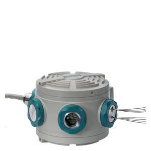
The MicroSAM is a miniaturized process gas chromatograph (GC) in an Ex d enclosure. Through consistent use of microsystem technology (silicon wafer technology), all analytical components are concentrated in the smallest possible area. The design particularly enables a distributed installation close to the process.
Дизайн
Enclosure
- EEx d version standard
- Heating adjustable from 60 to 165 °C (isothermal)
- Decentralized installation close to sampling point
Analytical module
The compact analytical module contains all the functional components of a chromatograph. The MicroSAM works with:
- Live injection
- Valveless live switching on microchip basis
- Standardized analytical modules
- Multidetection through use of up to 8 micro thermal conductivity detectors (TCDs) in the smallest possible area (e.g. on all column/purging outputs and injection)
Функции
Live injection
The MicroSAM has a two-stage injection system. Using a micro injection valve, a defined quantity of sample is first brought up to the carrier gas pressure. This eliminates the pressure-dependent error in the dosing quantity present with conventional systems. In the second stage, the sample is transferred to the column by a valveless micro injection system (live dosing). The result is an "active" injection.
The injection volume can be varied time-controlled, and exactly matched to the column requirements.
Valveless live column switching
Because of the high dead volume of conventional valves, only the valveless version can be considered for a miniaturized system. In this case, the generation of differences in flow using several electronic pressure regulators at appropriate positions of the column setup causes a change in the flow directions. (The system operates according to the Wheatstone principle, but pneumatically.) The functions "Cut" and "Backflushing" can then be implemented free of dead volume.
The column system
The column system consists of two or three capillary columns connected in sequence. Micro TCDs or micro live circuits are installed in sequence ("inline") upstream and downstream of the individual columns. Three electronic pressure regulators supply the columns with carrier gas and carry out the switching functions (injection, backflushing and cut).
By using narrow-bore capillary columns, the separation at high resolution is carried out within a much shorter time, approx. factor 2 to 3 compared to standard capillary columns.
Electronic pressure regulators
A high pressure stability together with rapid changing rates in the hPa range are required for precise and fast switching. This is achieved in the electronic pressure regulators by means of a piezo actuator.
Detector
The micro TCDs (based on silicon wafer technology) work on the principle of continuous measurement of the different thermal conductivities of the carrier gas and the components to be measured.
The measurement can be carried out without falsification by avoiding catalytic effects on the heating wires and maintaining a constant flow velocity. This permits consistent in-line detection, i.e. without qualitative or quantitative losses of substances.
Application modules
The application modules contain live injection and live switching. The modules D06, D08 and D11 have one separating column less than the modules D01, D02 and D09. The modules D06, D08 and D11 have one detector less than the modules D01 and D02. The application modules are suitable for separation of the components described below. However, when defining the suitable application module for an actual, customer-specific measuring task, technical evaluation by our Support Team is required.
D01, D02 and D08:
These modules contain separating columns that can be impaired in their separating performance by humidity in the carrier gas. For this reason, a carrier gas dry filter (filter set: order no. A5E00400116) is integrated for these modules on the support bracket of the MicroSAM or supplied as a separate part as standard.
The application modules are suitable for separation of the components described below.
Detector | Column 1 | Detector | Column 2 | Detector | Circuit | Column 3 | Detector | |
|---|---|---|---|---|---|---|---|---|
D01 | ||||||||
Injection | TCD | Sil5 C3, C4, C5, C6+ | TCD | PoraPLOT/Porabond Q CO2, C2, H2S, H2O | TCD | Live | Molecular filter H2, (Ar+O2), N2, C1, CO | TCD |
D02 | ||||||||
Injection | TCD | Sil5 C5+ | TCD | SilicaPLOT C2, C3, C4 (saturated, unsaturated), C5+ | TCD | Live | Molecular filter H2, (Ar+O2), N2, C1, CO | TCD |
D09 | ||||||||
Injection | - | Sil5 Non-polar aromatic and aliphatic hydrocarbons | TCD | Sil5 Non-polar aromatic and aliphatic hydrocarbons | TCD | Live | Porabond Q All components except molecular filter components | TCD |
Application modules D01, D02 and D09
Detector | Column 1 | Detector | Circuit | Column 2 | Detector | |
|---|---|---|---|---|---|---|
D06 | ||||||
Injection | TCD | Sil5 Non-polar aromatic and aliphatic hydrocarbons | TCD | Live | Sil5 Non-polar aromatic and aliphatic hydrocarbons | TCD |
D08 | ||||||
Injection | TCD | Porabond Q All components except molecular filter components | TCD | Live | Molecular filter H2, (Ar+O2), N2, C1, CO | TCD |
D11 | ||||||
Injection | TCD | RTX-5+ Non-polar aromatic and aliphatic hydrocarbons and medium-pole components such as chlorosilane | TCD | Live | SilicaPLOT C2, C3, C4, C5, C6 (saturated, unsaturated) | TCD |
Application modules D06, D08 and D11
Application
Various solution concepts are available:
- Adjustment without method development (on request)
- Run-out ex factory
The application modules are standardized. The functionality of the MicroSAM is proven with a specified carrier gas, exact setting of the oven temperature and the carrier gas inlet pressures, and with a standard calibration gas. The measured components and switching functions (live injection, backflushing, cut) are saved. - Commissioning on site
All application modules are standardized, i.e. the analytical hardware is defined and cannot be changed. The specific settings are carried out on site during commissioning.
- Run-out ex factory
- Adjustment with method development
Non-standardized applications require specific method development:
An optimum solution is elaborated on the basis of an existing specification and a selected calibration gas or with application of a customer sample.
Чертеж
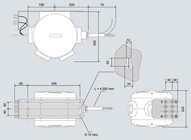
MicroSam, dimensions in mm
Особенности
- The distributed field installation reduces investment costs, and opens up new fields of application, e.g.:
- Installation in plant areas where mounting within an analyzer shed is not possible
- Installation at remote locations without extended infrastructure
- Reduction in laboratory analyses through online measurements
- Low space requirements in analysis cabinets reduce investment costs
- Low maintenance effort and gas/energy consumption reduce operating costs
- High-resolution capillary columns permit fast analyses
- Live injection permits representative sample injections
- Maintenance-free, valveless separating column switching with electronic pressure controllers
- The use of several micro thermal conductivity detectors (multidetection) provides exact measuring results and also validation possibilities
- Versatile networking possibilities for central maintenance and secure data transfer
- Remote monitoring with Windows-based software and Ethernet communication
- Simplified servicing through replacement of modules
Технические данные
MicroSAM | |
Design, housing | |
Weight | 15 kg |
Degree of protection | IP65 (NEMA 4X) |
Mounting | |
Installation on | Post, pipe or wall |
Distance from wall or next chromatograph | 300 mm (12") |
Distance from ceiling or floor | 200 mm (8") |
Explosion protection | ATEX and IEC Ex: II 2 G Ex d IIC T4 Gb Class I, Zone 1, Group IIB + H2 T4 Class I, Div 1, Groups B, C, D T4 Factory Sealed |
Support bracket | |
| 380 x 110 mm |
| 8 |
| 146 x 110 mm |
Electrical characteristics | |
Power supply | 24 V DC (18.5 ... 30.2 V) |
Power consumption | |
| 18 W |
| 60 W |
| IEC 61010 / DIN VDE 0411 |
EMC immunity | According to IEC 60801/DIN VDE 0843 |
| |
| 2 kV |
| 1 kV |
| 2 kV |
| |
| 1 kV |
| |
| 8 kV |
| |
| 10 V/m |
| According to CISPR 11 / EN 55011 / DIN VDE 0875 Limit class B |
| T2.5 A |
Gas inlet conditions | |
Permissible sample pressure | 10 … 60 kPa above atmosphere |
Sample flow | 20 … 100 ml/min |
Max. sample temperature | 120°C |
Solid components | < 0.1 mm |
Climatic conditions | |
Permissible ambient temperature | - 20 ... 50 °C (depending on oven temperature) |
Permissible storage/transport temperature | - 30 ... 70 °C |
Permissible relative humidity | Max. 90% |
Sample and injection | |
Sample streams | 3 |
Calibration sample streams | 1 |
Phase | Gaseous |
Required filtration | Degree of separation 99.99 % for < 0.1 μm particles |
Material with which the sample comes into contact | Stainless steel, fused silica, polyimide |
Injection | "Valveless" live injection |
| With multifunctional diaphragm valve |
| 2 ... 50 µl |
| 165 °C |
Oven | |
Number/type | 1/isothermal |
Purging with N2 | Possible |
Dimensions (DxH) | 160 x 10 mm |
Heating capacity | 20 W |
Temperature range | 60 … 155 °C |
Temperature stability | ± 0.1 K (60 ... 155 °C) |
Temperature accuracy | ± 3 K (60 ... 155 °C) |
Retention time variations per 10 °C change in ambient temperature | Approx. 0.3% |
Heating-up period from 30 ... 100 °C | 10 minutes |
Columns and gases | |
Column type | Capillary columns 0.15 ... 0.25 mm/internal |
Separating column switching | Multidimensional chromatography with backflushing and cut in live system |
Multifunctional diaphragm valve | For injection and backflushing |
Gas connections | Swagelok 1/8" |
Pressure regulators | Max. 4 single-channel electronic pressure regulators |
Solenoid valves for control of diaphragm valve | 2 NC contacts, 2 NO contacts |
Carrier gas | H2, N2, He, Ar |
| > 99.999% (5.0) |
| < 0.1 μm |
| Degree of separation 99.99% for < 0.1 μm particles |
| 10 ... 60 ml/min |
| 500 …700 kPa (g) 600 kPa (g) recommended Important: |
Instrument air | Not required |
Detectors, calibration and performance data | |
Detector type | TCD, max. 8 sensors |
Ambient temperature | Negligible |
Cell volume | 0.02 μl |
Calibration | Manual or automatic, single-level or multi-level |
Smallest measuring range | 1 000 ppm (application-dependent) |
Linear range | Typically > 104 |
Cycle time | Typically 30 … 240 s |
Electrical inputs and outputs | |
Basic equipment | |
| 4, freely usable (expandable by NAU or I/O Extender, see communication in "General information") |
| 4, 3 freely usable (expandable by NAU or I/O Extender, see communication in "General information") |
Interfaces | |
| 1 x Ethernet 10BaseT / TCP/IP |
| 1 x RS 485 or RS 232 / Modbus RTU, OPC (ODPC) over Ethernet |
Electronics | |
Communication and analytical controller (CAC) | |
| Intel 586 architecture |
| 128 MB |
| 64 MB |
| Windows CE 5.0 |
| Preinstalled. Modifications or upgrades for operation PC downloadable via network or locally |
Realtime signal processor (RSP) | |
| Motorola 68376, 20 MHz |
| 1 MB |
| 1 MB |
| Forth |
| Preinstalled. Modifications or upgrades downloadable via internal service interface |
Controller | |
| 3 |
| 1 |
|
|
|
|
Recommended operator panel | |
| Desktop or laptop |
| At least Pentium III |
| ≥ 800 MHz |
| 1 x Ethernet |
| Windows XP or 7 |
| Gas chromatograph portal, from version 1.02 |
Дальнейшая информация
Support bracket
For easy mounting, incl. support for 8 gas connections consisting of:
- Mounting part: Dimensions: 380 mm x 110 mm (WxH)
- Bracket for gas connection; dimensions 146 mm x 110 mm (DxH)
Bracket on right side, mounted at right angle
The bracket is stipulated in the manual.
Exception
The bracket is not required if the MicroSAM is fitted in a protective casing approved by Siemens. In this case, however, shipping of the unit is only permissible in this protective casing.
Sample streams
For up to 4 sample streams (including calibration stream); e.g. 3 sample streams + 1 calibration stream; controlled by 4 internal digital outputs (relay contact 0.4 A / 24 V DC)
Pos. 8_0: For gaseous sample
This position contains a basic unit prepared for integration of the analyzer modules.
Pos. 8_8: Standard UKOG
Individual customers standard.
Pos. 9_B: Workstation operating software
The workstation operating software can only be ordered together with MicroSAM. Workstation operating software is required for each gas chromatograph network.
C01 – Method development and application
Comprehensive and specific development of the method is required for the tasks.
The measured components and switching functions are entered completely using a customer sample (or a specially selected calibration gas). Proof of repeatability is carried out in accordance with the customer specification.
If a natural gas analyzer for calculation of the calorific value is ordered, the evaluation parameters are specifically optimized for the natural gas analysis.
The required BASIC programs (H0X) are installed in the gas chromatograph.
The retention time window C6+ is set to the measured components n-C6 to C9.
J0X – Acceptance and customer information
The scope of delivery is checked and the documentation and operation of the device explained in detail during the factory acceptance.
This also comprises presentation of the analytical solution including communication, chromatograms, piping plan and gas path plan. If present, inspection of the sample preparation and discussion of the documentation are carried out.
Please supplement the order for J02 to J04 by the desired option from E0x.
Only experienced MicroSAM users should consider the option for starting up the MicroSAM in the context of remote acceptance, e.g. using a telephone conference (on request).
E0x – Repeatability test
Proof of repeatability over a period of 2 h is included as standard. Longer proof of repeatability for the unit can be ordered using the supplements E02 to E04.
F01 – Data transmission over Modbus
Implementation and testing of a Modbus table for Modbus communication (RS 232 / RS 485 RTU).
K0X – Inputs/outputs via I/O Extender
The MicroSAM basic unit provides four digital inputs and outputs. If more interfaces are required, these are provided by the I/O Extender. It should be noted, however, that the I/O Extender requires two device-internal digital inputs and outputs. The I/O Extender solution can generate up to 12 additional analog outputs for the chromatograph (further inputs and outputs on request). The latest generation of NESSI components for sample preparation can also be controlled. The max. cable length between MicroSAM (including master cable) and I/O-Extender must not exceed 20 m. A 24 V DC power supply is required for the I/O Extender. This must be provided separately, but can also be covered by the power supply of the MicroSAM.
Note:
If the delivery is to include a protective casing from the Set CV range, please refer to this category in Catalog PA 01. There you can find more information on the I/O Extender and its specification within this total solution.
K02 or K04 standard packets 1/3
This position includes:
- Mounting rail
- An I/O Extender module
- Protective casing, Ex e with standard cable glands and terminal block; 170 x 227 x 131 mm (L x W x D)
The delivery package of the I/O Extender solution for Class I Div 2 contains adapters (female thread 1", 3/4", 1/2" for fitting of conduits) which are suitable for cable glands in accordance with this hazardous area.
K03 or K05 standard packets 2/4
This position includes:
- Mounting rail
- Three I/O Extender modules
- Protective casing, Ex e with standard cable glands and terminal block; 340 x 170 x 131 mm (L x W x D)
The delivery package of the I/O Extender solution for Class I Div 2 contains adapters (female thread 1", 3/4", 1/2" for fitting of conduits) which are suitable for cable glands in accordance with this hazardous area.
H0X - Various calculations and functions using BASIC interpreter integrated in the GC
The BASIC programs are either preset ex-works or can be created and modified by the customer.
H01 – MicroSAM BASIC Editor
The MicroSAM BASIC Editor allows individual programming of calculations and functions by the user.
H02 - Application setup: Natural gas - calculation in accordance with ISO 6976-95
The following physical variables must be calculated in accordance with the standard: calorific value, heating value, Wobbe index, density, relative density.
The calorific value is calculated as standard in MJ/m3 on a molar basis referred to the reference temperature 25 / 0 °C (combustion/metering temperature). Calculation on the basis of other reference variables or tables (in accordance with the standard) requires unambiguous specification by the customer.
The BASIC program is preset ex works; a customer modification is only possible with the supplement H01.
H03 - Application setup: Natural gas - calculation in accordance with GPA2172-96
The following physical variables must be calculated in accordance with the standard: calorific value, relative density and compressibility factor.
The calorific value is calculated as standard in BTU/ft3 (S) referred to the reference temperature 60 °F. Calculation on the basis of other reference variables or tables (in accordance with the standard) requires unambiguous specification by the customer.
The BASIC program is preset ex works; a customer modification is only possible with the supplement H01.
H04 - Application setup: Natural gas - calculation in accordance with GOST22667-82
The following physical variables must be calculated in accordance with the standard: calorific value, heating value, Wobbe index, relative density.
These parameters are calculated based on the physical properties of the pure components. As a special feature, the methane concentration is defined as the residual value in this operating mode.
The BASIC program is preset ex works; a customer modification is only possible with the supplement H01.
H05 - Application setup: Customer-specific calculations and functions
An unambiguous description of the task is required in order to guarantee correct functioning of the program.
The BASIC program is preset ex works; a customer modification is only possible with the supplement H01.
The supplement H03 is only possible together with C0X.
Calibration gas I in vol.% | Calibration gas II in vol.% | Calibration gas III in vol.% | |
|---|---|---|---|
1.2-butadiene | – | – | 0.1 |
1.3-butadiene | – | – | 0.1 |
1-butene | – | – | 0.1 |
2.2 dimethylpropane | 0.3 | 0.3 | – |
cis-2-butene | – | – | 0.1 |
Cyclopropane | – | – | 0.1 |
Ethane | 4 | 4 | 0.1 |
Ethene | – | – | 0.1 |
Ethine | – | – | 0.1 |
Ethyl acetylene | – | – | 0.1 |
Helium | – | – | Remainder |
Isobutane | 0.5 | 0.5 | 0.1 |
Isopentane | 0.3 | 0.3 | – |
Isopentane | – | – | 0.1 |
Carbon dioxide | 2 | 2 | – |
Methane | Approx. 85 | Approx. 84.5 | 0.1 |
Methyl acetylene | – | – | 0.1 |
n-butane | 0.5 | 0.5 | 0.1 |
n-heptane | 0.05 | 0.05 | – |
n-hexane | 0.05 | 0.05 | 0.1 |
n-pentane | 0.3 | 0.3 | 0.1 |
Propadiene | – | – | 0.1 |
Propane | 2 | 2 | 0.1 |
Propene | – | – | 0.1 |
Oxygen | 0.1 | – | – |
Nitrogen | 5 | 5 | – |
trans-2-butene | – | – | 0.1 |
Vinyl acetylene | – | – | 0.1 |
Hydrogen | – | 0.5 | – |
Standard calibration gases for system test and run-out

Box with I/O Extender


 Ответ от производителя может занять до 5 дней и более.

