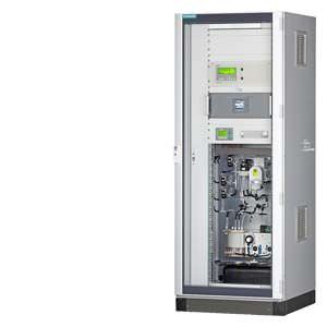
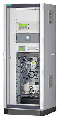
Set CEM CERT Siemens

Область применения
- Emission monitoring of power plants fueled with solid, gaseous or liquid fuels
- Emission monitoring of so-called TA Luft plants (e.g. emission monitoring of glass melting furnaces or steel plants)
- Emission monitoring in crematorium facilities (27. BImSchV)
Обзор

Set CEM CERT is a standardized and certified continuous emission monitoring system which is suitable for use in many plants requiring European legislation (13. BImSchV, 27. BImSchV, TA Luft, 2001/80/EC and IED 2010/75/EC, Annex V) approval. The innovative CEMS meets the current quality standards of EU directives EN 14956, EN 15267 and EN 14181 (QAL1/2/3, AST).
Дизайн
Tested component design
The complete system consists of the following tested individual components:
- Sampling probe: M&C, type: SP2000; Bühler/Siemens, type: GAS222/7MB1943-2F
- Heated sample gas line: Winkler/Siemens, type: 7MB1943-2A
- Temperature controller: Siemens, type: SIRIUS
- Two-stage compressor gas cooler: M&C, type: CSS; Bühler, type: EGK 2-19
- Sample gas pump: Bühler/Siemens, type: P2.3/7MB1943-3C
- NOX converter: M&C, type: CG-2; Bühler/Siemens, type: BUENOX/7MB1943-2D
Performance-tested measuring ranges
Component | Analyzer module | Smallest certified measuring range | Additional measuring ranges | |
CO | U23-7MB2355 | 0 ... 200 mg/m³ | 0 ... 750 / 3 000 mg/m³ | |
U23-7MB2357 | 0 ... 200 mg/m³ | 0 ... 750 / 3 000 mg/m³ | ||
U23-7MB2358 | 0 ... 250 mg/m³ | 0 ... 1 250 mg/m³ | ||
NO | U23-7MB2355 | 0 ... 150 mg/m³ | 0 ... 750 / 2 000 mg/m³ | |
U23-7MB2357 | 0 ... 150 mg/m³ | 0 ... 750 / 2 000 mg/m³ | ||
U23-7MB2358 | 0 ... 400 mg/m³ | 0 ... 2 000 mg/m³ | ||
(in test phase) | UV600 | 0 ... 50 mg/m³ | 0 ... 100 / 1 000 / 2 000 mg/m³ | |
SO2 | U23-7MB2355 | 0 ... 400 mg/m³ | 0 ... 2 000 mg/m³ | |
U23-7MB2357 | 0 ... 400 mg/m³ | 0 ... 2 000 mg/m³ | ||
U23-7MB2358 | 0 ... 400 mg/m³ | 0 ... 2 000/7 000 (in operation) mg/m³ | ||
(in test phase) | UV600 | 0 ... 75 mg/m³ | 0 ... 130 / 1 500 / 2 000 mg/m³ | |
NO2 | (in test phase) | UV600 | 0 ... 50 mg/m³ | 0 ... 500 mg/m³ |
O2, (paramag.) | U23 | 0 ... 25 vol % | ||
O2, (electrochem.) | U23 | 0 ... 25 vol % | ||
Функции
The complete tested modular measuring equipment is composed of the sampling probe, the heated sample gas line, a two-stage sample gas cooler, a gas pump and the multi-component analyzers, ULTRAMAT 23 and SIPROCESS UV600.
An electrochemical or a paramagnetic oxygen measuring cell can be used for the measurement of oxygen.
The gas path splits in parallel after the sample gas cooler. This separately supplies each analyzer with sample gas. One advantage for maintenance is that each analyzer can be individually serviced without affecting the other. The sample gas coolers used have a moisture alarm in case of malfunction. For additional protection, each analyzer is protected by a condensation barrier, which stops the gas flow if moisture penetrates. This guarantees optimum protection for gas analyzers.
For semi-automatic calibration of the zero and calibration gases, a 3/2-way solenoid valve is installed between the first and second cooling stages. The valve can also be used for AUTOCAL calibration of the ULTRAMAT 23 (fully automatic timing) as well as by the integrated PLC (LOGO module).
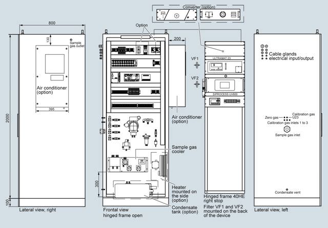
Чертеж

Figure contains options, dimensions in mm
Особенности
- The tested measuring ranges can be selected for a variety of ranges to ensure use in different areas of application for the CEMS (TÜV approved).
- The complete modular package allows the certified use of system components from different manufacturers (TÜV approved).
- Simple and fast to configure
- Very low costs of procurement and operation
Modular design
- Up to 2 analyzers with different measuring ranges can be configured
- Selection of versions for indoor or outdoor installation
- Selection of sample gas cooler and NOX converter from leading manufacturers
- Electric heaters and air conditioners can be configured to extend the ambient temperature range
- Selection of versions with appropriate sampling probes, heated sample gas lines
Технические данные
Climatic conditions | |
Ambient temperature | +5° ... +40 °C (standard) |
| Min. -5 °C |
| Min. -15 °C |
| Max. +52 °C |
Relative humidity | 75 % (annual average), non-condensing |
Sample gas conditions | |
Max. sample gas pressure at inlet to sample preparation system | 500 hPa (mbar) |
Max. moisture content in sample gas | 17 vol % (cooler type: CSS) |
Sample gas temperature | Max. 200 °C at cabinet entry |
Sample gas flow | Approx. 60 l/h per analyzer module |
Sampling probe (standard) | Dust load: < 2 g/m3 |
Mounting flange: DN 65, PN 6, form B | |
Including temperature controller with PT100 | |
With internal sampling tube, stainless steel, length: 1 m (can be shortened) | |
With filter in probe, to 600 °C | |
Sampling probe for higher temperatures and in other materials (optional) | On request |
Sample gas line, electrically heated | Max. 35 m, longer lengths on request |
Sample gas must not be flammable or explosive. | |
Power supply | |
Supply 1 | 115 V AC, 50 … 60 Hz (-15 %, +10 %) |
Supply 2 | 230 V AC, 50 … 60 Hz (-15 %, +10 %) |
Supply 3 | 400 V AC, 50 … 60 Hz (-15 %, +10 %) |
Power | 4 000 VA max. |
System design | |
Fusing of electronic consumers | 1-pole or 2-pole (selectable) |
Sample gas cooler | 2-stage |
Output signals | 4 … 20 mA (corresponding to the analyzer information) |
Additional digital inputs and outputs via PLC (LOGO) | |
Color | RAL 7035 |
Weight | Approx. 160 kg |
Sheet-steel cabinet/frame | Indoor installation |
GRP cabinet | Outdoor installation |
Explosion protection classification | Installation outside the Ex zone |
Degree of protection | IP 54 (avoid direct sunlight for outdoor installation) |
Calibration | Semi-automatic; AUTOCAL freely adjustable on U23 up to max. 24-hour interval |
Detailed information on the analyzers You can find detailed information on the analyzers:
| |
Dimensions | |
Sheet-steel cabinet (with base) for indoor installation | 2 000 x 800 x 800 mm (H x W x D) |
GRP cabinet (with base) for indoor installation | 2 060 x 900 x 800 mm (H x W x D) |
500 mm spacing on the right or left must be provided for the cable inlet and connection of the heated sample gas line. | |


 Ответ от производителя может занять до 5 дней и более.

