D-FL 100 volume flow measuring system Siemens
Область применения
As in-situ measuring system, the measuring equipment determines the measured values without sampling directly in the duct through which gas is flowing.
Areas of application
- Volume flow measurement at high temperatures
- Plants with small or large flue cross-sections
- Volume flow measurement at high pressure
Approvals
- Suitability-tested by the TÜV Cologne, test report 936/800006/A
- Itemized in the list of suitable measuring devices for continuous emission measuring
- MCERTS
Обзор

The D-FL 100 volume flow measuring system measures the flow rate in dry emissions with a probe using the differential pressure principle.
Дизайн
System components D-FL 100
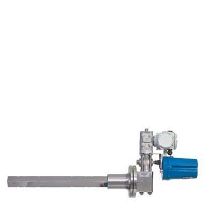
Dynamic pressure probe
Each dynamic pressure probe of type D-FL 100 is a customized product for the respective measuring location. Three different sizes are available depending on the length of the planned measurement path:
- System 1: 22 x 24 mm2 for 0.4 to 2 m length, with one-sided (max. 1 m) or two-sided mounting
- System 2: 50 x 53 mm2 for 0.4 to 4 m length, with one-sided (max. 1.5 m) or two-sided mounting
- System 3: 90 x 100 mm2 for 0.4 to 8 m length, two-sided mounting
Adapter
The cross-over cock is either connected by an adapter to the differential pressure transducer directly on the probe (not for system 3) or via a hose or tube connection.
Cross-over cock
Cross-over device for the backpurging of the dynamic pressure probe
Differential pressure transducer
The transducer is delivered with factory set defaults for the order-specific configuration. The zero point should be calibrated after the installation.
Counter-support
A counter-support is required for a probe mounted on two sides. The counter-support supports the probe not only mechanically, but also enables the compensation of the temperature-dependent longitudinal expansion of the probe.
Mounting tubes with flange
Mounting tubes made of stainless steel 1.4571, adapted to the plant conditions, are available in various lengths. A single flange is required for a one-sided probe; otherwise two flanges are always required.
Optional:
Evaluation unit
The evaluation unit D-FL 100-20 evaluates the measured signal from the differential pressure transducer. A 4 to 20 mA current signal is available as measured value output. A Modbus interface according to VDI 4201 for the connection of an emission evaluation calculator with digital interface is available in addition to the 4 to 40 mA current signal output. The front panel contains five LEDs and one USB port. The LEDs signal the system''s current status/operating state.
The various parameters, such as standard density, substitute values for pressure and temperature in the exhaust gas duct, k-factor and measuring ranges are input via the USB port with the help of a PC or the associated software D-ESI 100.
Software D-ESI 100
Software for assigning parameters, visualizing the measured data, and carrying out AST, QAL2 and QAL3 for D-FL 100-20.
The D−ESI 100 can be parameterized, maintained and (when faults occur) analyzed via the USB port with the help of a PC and the associated software.
Universal control unit D-ISC 100 with evaluation unit D-FL 100-20
The connected equipment can be operated and configured conveniently using the D-ISC 100. The display provides an immediate overview of the current measured values and the status of the measuring instruments.
Automatic back purging unit
An automatic back purging device to keep the measuring openings clean is available for applications with high dust loads.
Weather protection covers
A weather protection cover is available to protect the probe head and the back purging control when the measuring system is installed outdoors.
Additional options:
- Absolute pressure transducer
- Temperature transducer
- Special designs in other materials for applications with particularly aggressive exhaust gases or higher gas temperatures: Standard material for probe stainless steel 1.4571, depending on measurement task also Hastelloy, Inconel or other materials
- dP transducer in Ex-version
Функции
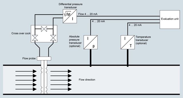
The D-FL 100 measuring system operates according to the mechanical action principle. The probe has two separate chambers, between which the flow builds up a differential pressure. Taking account of the other flow parameters such as absolute pressure and temperature, for example, the volume flow can be converted from operating to standard conditions with the help of the D-FL 100-20 evaluation unit.
Особенности
- Measuring of emission speed
- Adjustable parameters
- Versions with or without counter-support and for point measurement
- Calculation of volume flow at standard conditions with evaluation unit D-FL 100-20
- Maintenance interval 6 months
- Automatic backpurging device (optional)
Технические данные
Measuring system D-FL 100 | |
Measurements |
|
Measuring ranges |
|
Measuring principle | Differential pressure |
Sample gas temperature | Above dew point up to 450 °C, optional up to 850 °C |
Sample gas pressure | -200 ... +200 hPa, optional higher |
Duct diameter | 0.4 ... 8 m |
Ambient temperature | -20 ... +50 °C |
Degree of protection | IP65 |
Measured value output | 0/4 ... 20 mA, 500 Ω |
Digital outputs | 2 relay outputs, permissible load 48 V/0.5 A |
Digital inputs | None |
Accuracy | < 2 % of the measuring range |
Detection limit | < 3 m/s |
Reference point drift | < 0.5 % of measuring range / month |
Zero point drift | < 0.5% of measuring range / month |
Auxiliary power | 18 ... 32 V DC/1 A, 90 ... 264 V AC, 48 ... 62 Hz, 100 VA |
Dimensions | |
| 380 x 160 x (300 + probe length) mm |
| 0.4 ... 2 / 0.4 ... 4 / 0.4 ... 8 m |
Weight | 32 kg + 6.8 kg/m probe length |
Purge-air supply (optional) | 6 ... 8 bar for back purging |
1) Optional pressure and temperature correction
Дальнейшая информация
Please consult your Siemens sales partner for information on how to correctly configure and order a D-FL 100 measuring system for a Siemens CEMS project.


 Ответ от производителя может занять до 5 дней и более.

