Set CV Siemens
Область применения
For the chromatography industry, the natural gas market is one of the fastest growing in the world. There are a variety of reasons for this. While global energy requirements are increasing, there is a parallel trend of fossil fuel reserves being depleted. Natural gas is one type of fossil fuel that can still be found in vast, untapped reserves. In addition to this, the market is becoming increasingly liberalized, and the number of participants has risen considerably as a result - from the production stage, across the entire distribution network, right through to the end customer. In turn, this has generated more transfer points at which the quality and quantity of natural gas need to be determined for accounting purposes.
The market requires a reliable complete system which is specially designed for natural gas. With the Set CV, Siemens offers a system that covers all the requirements of such applications, from sampling to pressure reduction, sample preparation and determination of quality, supplying carrier and calibration gases, right through to expansion of the communication interfaces.
The set offers various modules to cover market requirements. Using the different versions, the set can be adapted, and the modules can be freely-combined.
Such a system can be used wherever the quality of natural gas has to be determined. For example, during the conditioning of natural gas and feeding into the pipeline network, during transportation and distribution in the network, and when extracting it for supply purposes.
Обзор
The Set CV (Calorific Value) is a standardized system for determining the quality of natural gas with SITRANS CV and MicroSAM.
Дизайн
Standardization of systems means good clarity and simple facilities for configuration. Different versions mean that it is possible to appropriately adapt the system to the requirements. The modules can be combined as desired. Standardization also means that not all imaginable versions are included, and that special requirements such as armored cables, customer-specific documentation, specific conductor labeling, or certificates such as CE or 31B cannot be implemented at all, or not without an extra charge.
The design is divided into the following standard modules: sampling, pressure reduction, sample preparation system, SITRANS CV, gas supply, calibration gases.

General information
The set can be dimensioned for a 230 V AC or 115 V AC power supply. It is not possible to switch between supplies.
The gas connections can be supplied with either metric or imperial dimensions.
On the metric line, the gas connections are in the form of metric clamping ring glands with a diameter of 3 mm. The imperial line contains gas connections in the form of imperial clamping ring glands with a diameter of 1/8 inch. The pipes between the sampling probe, pressure reduction, sample preparation device, and SITRANS CV are optionally available. The system is generally designed for temperatures between -20 and +55°C in areas with a risk of explosions. When provided with heating, the system can also be used down to -30 °C. The natural gas to be measured should be in a stable gaseous form, dry and clean.
Sampling probe
The basic components of a sampling probe are a lance, process connection, process isolation and, if needed, pressure reduction. The high-pressure version is not supplied pre-assembled.
Lance
A representative sample should be taken from the central third of the pipeline. With a lance length of 1 m it is therefore possible to extract a sample from a pipeline with a diameter of up to 1 600 mm. In addition, two versions with different types of lance diameter are available. On the one hand, a pipe whose outer diameter is 6 mm and inner diameter is 2 mm. And on the other, a pipe whose outer diameter is 12 mm and inner diameter is 8 mm. The lance can be supplied in a permanently installed or removable state (not for 12 mm).
Process connection
There are four versions for the flange connection to the pipeline. Flange DN 65 PN16 Form C for pressures up to 1 600 kPa, flange ANSI 2" for pressures up to 300 lbs RF as well as flange DN 65 PN160 Form E for pressures up to 16 000 kPa and flange ANSI 2" for pressures up to 2 500 lbs RF
Process isolation
It may be necessary to isolate the natural gas line from the system for maintenance and repair work. To do this, you can select either a simple stopcock or a double block and bleed structure. While the stopcock is a cost-effective solution for minimum requirements, the double block and bleed structure stands for enhanced safety, as it has two valves that prevent any gas from being transferred further.
High-pressure reduction on the primary side
Pressure can be reduced in three ways: directly at the probe (primary side), in an external casing with a pressure reduction unit (primary side), or in the sample preparation system (secondary side).
If the sample preparation system and the natural gas chromatograph are installed directly next to the sampling point, the high-pressure reduction can be implemented in the sample preparation system. The pressure should always be reduced as close to the sampling point as possible in order to keep the dead volume as small as possible. The permissible sample and calibration gas pressure is 10 to 60 kPa above atmospheric pressure. Notice: Sample must not contain ethine!
The incoming carrier gas pressure must range from 500 to 700 kPa (g). 600 kPa (g) is recommended. Important: A continuous carrier gas supply is required for error-free operation (frequent carrier gas failure has a negative effect on the service life of the detectors and the device-internal pressure settings). In addition, an external two-stage pressure regulator for the carrier gas pressure is strongly recommended.
Heated and unheated pressure reduction units are available in the external casing for high-pressure reduction on the primary side. Pressure reduction in the external casing is suitable for combination with the permanently installed and retractable standard probe. The heated pressure regulators have a power consumption of 150 W, and reliably maintain the sample in a gaseous state.
Special probe with high-pressure reduction
A third option offers an alternative to the two standard probes: a permanently installed probe with integrated separation of aerosols (so-called BTU diaphragm) in the pipeline and a pressure reduction unit. The lance is integrated in this at a depth of 228 mm. The protection pipe has an outer diameter of 22.8 mm. The lance and pressure reduction do not need to be separately defined.
Heated pipeline
To ensure that the sample is maintained in a gaseous state, it is recommendable to use a heated sample gas line – for example, between the sampling point and the sample preparation system. The pipeline is encased in a PE corrugated hose with an outer diameter of 43 mm. The self-regulating maintenance temperature is around 80 °C. The electrical connection is in the terminal box.
The power consumption is approx. 38 W/m.
Pipe base for enclosure attachment
A hot-dip galvanized 2" pipe base, 1 700 mm high, with mounting brackets and joining sheet enables free-standing mounting of the protective casing.

Sample preparation
The permissible sample and calibration gas pressure is 10 to 60 kPa above atmospheric pressure. Notice: Sample must not contain ethine!
The incoming carrier gas pressure must range from 500 to 700 kPa (g). 600 kPa (g) is recommended. Important: A continuous carrier gas supply is required for error-free operation (frequent carrier gas failure has a negative effect on the service life of the detectors and the device-internal pressure settings). In addition, an external two-stage pressure regulator for the carrier gas pressure is strongly recommended.
The basic configuration of the sample preparation system for a stream includes a stopcock, 0.5 µm filter, flowmeter for the fast loop, pressure-relief valve, 3/2-way solenoid valve with sealed cable for automatic switching between calibration gas and sample gas, and a terminal box for connecting the solenoid valve. This solenoid valve must either be protected by the customer at 0.5 A, or a ready-assembled terminal box with power supply and fuses can be ordered from the list of supplementary items.
There are also a number of other options for modifying the basic configuration.
Secondary pressure adjustment
The pressure adjustment unit with unheated pressure regulators can be ordered for one, two and three sample flows. This type of structure meets the minimum secondary pressure adjustment requirements. Please note that a reduction in pressure cools the sample down considerably, which can cause moisture to condense if the dew point is fallen below.
Another alternative, however, is pressure adjustment with a heated pressure regulator (150 W) for one, two or three sample streams. Heating the sample ensures that it remains in a gaseous state. The Joule-Thomson effect is thus compensated. The regulators can reduce pressures from 16 to 100/170 kPa.
If the pressure is to be reduced directly at the sampling probe or in an external casing outside the sample preparation system, no further pressure reduction is required during sample preparation.
Sample injection
Where sample injection is concerned, straightforward and safety versions are available for between one and three streams.
Considered simply, sample injection is carried out for one, two or three streams using one solenoid valve per sample stream (cascade connection). Its job is to block any gas flows that are not required without preventing the desired gas from flowing. A 0.5 A fuse is required per solenoid valve and flowmeter. These are available in the ready-assembled terminal box.
The safety version of the sample injection system for one, two or three streams with double block and bleed technology enables the sample to be switched over, which in turn allows clean separation between gas streams by partially closing and venting the line. Since two valves are used to prevent the flow of gas that is not to be measured, rather than just one, the functional safety of the system remains at an optimum level for a long time. In addition, 0.5 A fuses are required for the sample valves and calibration valve. These are included in the electrical connection (supplementary item).
Monitoring the sample gas monitoring chromatograph (GC)
The sample flow to the GC can also be monitored electronically as an option. An alarm signal is output when necessary. A switch disconnector for the power supply is also required; this can be ordered along with the ready-assembled terminal box.
Protective casing/mounting plate for sample preparation system
The sample preparation system is available mounted either on a plate, in the protective casing, or in the heated protective casing.
The stainless steel mounting plate, measuring 682 x 482 x 3 mm (H x W x D), is suitable for wall mounting. The system components selected are mounted on the plate and supplied with all pipes and wires installed.
The unheated protective transmitter box, made from fiber glass-reinforced plastic and suitable for wall mounting, measures 800 x 600 x 480 mm (H x W x D) and is fitted with stainless steel hinges, quick-release locks, safety glass windows and a stainless steel mounting plate.
The system components selected are mounted and supplied with all pipes and wires installed in the protective casing.
It is also possible to provide a heater in the protective transmitter box which can be controlled between 10 and 40 °C in steps of 5 degrees. The system components selected are mounted and supplied with all pipes and wires installed in the protective casing. The heater has a capacity of 400 W.
Aerosol filter/glycol filter
These filters have the task of removing any impurities that may have been introduced into the natural gases by aerosols or glycols, thus providing an additional level of safety for the SITRANS CV and, therefore, the system functionality. The aerosol filter is supplied with 5 replacement diaphragms and the glycol filter with 10 replacement cartridges.
Manual laboratory sampling
An additional control valve permits manual laboratory sampling as an option. When not in use, it is fitted with a blanking plug on the output end.
Pipe base for enclosure attachment
A hot-dip galvanized 2" pipe base, 1 700 mm high, with mounting brackets and joining sheet enables free-standing mounting of the protective casing or the mounting plate as an alternative to wall mounting.
Protective top cover
Another option is a protective top cover made from fiber glass-reinforced plastic and supplied with mounting brackets, for protection against solar radiation and storms. It must be mounted to a pipe base.
Heated sample gas line
To prevent condensation of the sample, it may be necessary to use a heated prepared pipeline – for example, between the sample preparation device and SITRANS CV/MicroSAM. The pipeline is encased in a PE corrugated hose with an outer diameter of 43 mm. The self-regulating maintenance temperature is around 80 °C.

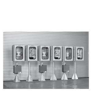
Example of single-stream sample preparation system: may deviate from the supplied system
SITRANS CV/MicroSAM
The core component of the Set CV is the GC SITRANS CV/MicroSAM (for more detailed information see catalog PA 01, section 3).
SITRANS CV/MicroSAM system components
Protective casing/plate for SITRANS CV/MicroSAM
The SITRANS CV/MicroSAM is available mounted either on a plate, in the protective casing, or in the heated protective casing.
The stainless steel mounting plate, measuring 682 x 482 x 3 mm (H x W x D), is suitable for wall mounting.
The unheated protective transmitter box, made from fiber glass-reinforced plastic and suitable for wall mounting measures 800 x 600 x 480 mm (H x W x D) and is fitted with stainless steel hinges, quick-release locks, safety glass windows and a stainless steel mounting plate.
The protective casing can also be supplied with heating as an option. The heating can be adjusted between 10 and 40 °C, in increments of 5. The system components selected are mounted and supplied with all pipes and wires installed in the protective casing. The heater has a capacity of 400 W.
Terminal box
There are five connection options in total to choose from:
The simplest option is the interface in accordance with SITRANS CV/MicroSAM (open cable end).
The terminal box measuring 340 x 170 x 91 mm (H x W x D) is made from polyester resin. The scope of delivery includes terminals, isolating terminals, cable glands and a PE rail. If ordered with the pipe base add-on part, the terminal box is supplied attached to the base, and the scope of supply includes 2.5 mm² terminals for connection by the customer and M16/M20 cable glands. The power supply is 24 V DC. The terminal box is not suitable for connecting a heater, flow meter with limit value transmitter, and Double Block and Bleed (DB&B).
The terminal box measuring 360 x 360 x 190 mm (H x W x D) is made from painted sheet steel. The scope of delivery includes switch amplifiers, terminals, and cable glands. If ordered with the pipe base add-on part, the terminal box is supplied attached to the base, and the scope of supply includes 2.5 mm² terminals for connection by the customer and M16/M20 cable glands. The power supply is 24 V DC. The terminal box is not suitable for connecting a heater and DB&B.
The terminal box, including switch amplifier and a power supply (115 V AC or 230 V AC, not switchable), measuring 360 x 360 x 190 mm (H x W x D), is made from painted sheet steel. The scope of delivery includes terminals, 0.5 A fuses, terminals, cable glands and a PE rail. If ordered with the pipe base add-on part, the terminal box is supplied attached to the base, and the scope of supply includes 2.5 mm² terminals for connection by the customer and M16/M20 cable glands. The terminal box is not suitable for using DB&B.
The terminal box, including switch amplifiers and a power supply (115 V AC or 230 V AC, not switchable), measuring 360 x 360 x 190 mm (H x W x D), is made from painted sheet steel. The scope of delivery includes isolating terminals, 0.5 A fuses, terminals, cable glands, relays and a PE rail. If ordered with the pipe base add-on part, the terminal box is supplied attached to the base, and the scope of supply includes 2.5 mm² terminals for connection by the customer and M16/M20 cable glands.
Gas supply
A gas chromatograph requires calibration and carrier gases. Therefore the set offers various options with regard to gas connection, gas cylinder design, and calibration gases. Either individual components or complete systems can be ordered.
Cylinder pressure reducer, separate
The cylinder pressure reducer for calibration gases is supplied separately. It is made from stainless steel and has a cylinder connection conforming to DIN 477 No. 14 (calibration gas). The cylinder pressure reducer is also fitted with a gauge for primary and back pressure.
Contact gauge for supply gases
Two gauges with a 50 mm diameter and mounted on the battery pressure reduction station can also be ordered. The intrinsically-safe slot initiators in accordance with NAMUR must be operated via a switch amplifier. This is not included in the delivery. The line is in the terminal box on the station panel.
Heated line
A heated prepared line is available for heating the calibration gas line from the cylinder cabinet to the sample preparation device. The power consumption is 38 W/m with an outer diameter of 43 mm on the corrugated hose. The integrated heating system is self-regulating with a maintenance temperature of approximately 80 °C.
Automatic cylinder changeover switch with separate coils
The stainless steel automatic cylinder changeover switch, supplied on a mounting plate, is designed for back pressures of between 50 and 1 000 kPa and contains two coiled pipes for helium that conform to DIN 477. The maximum permissible cylinder pressure is 20 000 kPa. This version also includes a gauge for measuring primary and back pressure. A contact gauge cannot be fitted when supplied separately.
Simple supply unit
This simple supply unit consists of a hot-dip galvanized 2-inch pipe base, 2 200 mm high, with a fiber glass-reinforced plastic protective top cover as well as two cylinder holders and a cylinder changeover switch. The gas cylinders are not included in the basic scope of supply.
Painted sheet steel gas cylinder cabinet
This version is supplied with the automatic cylinder changeover switch and coils, as well as the stainless steel calibration gas cylinder pressure reducer in a sheet metal cabinet.
The gas cylinder cabinet has room for two 50 l cylinders and one 10 l calibration gas cylinder. The dimensions are 2 050 x 1 250 x 400 mm (H x W x D). It contains the cylinder station, a stopcock for carrier gas, cylinder holder and pipe coils for the gas cylinders. The cabinet pipes are fully installed and the cabinet is equipped with bulkhead fittings for carrier gas, calibration gas and exhaust gas from the pressure relief valves.
As an option, this gas cylinder cabinet can also be supplied with heating from a heating sleeve for a 10 l calibration gas cylinder at 20°C retaining temperature. The cylinder head is heated separately, in a fiber glass-reinforced plastic enclosure. The cylinder pressure reducer is also located here. The heating sleeve prevents condensation from building up in the gas cylinder. To ensure seamless gas heating, a heated line for accepting the calibration gas is recommended.
Calibration gases
Six different calibration gases are available as standard.
Component groups | C6+ with O2 | C6+ without O2 | C6+ without O2 | C7+ without O2 | C6, C7, C8, C9 without O2 | Biomethane with H2 |
|---|---|---|---|---|---|---|
Special feature | Certified in acc. with PTB-A 7.63 | |||||
(mol %) | (mol %) | (mol %) | (mol %) | (mol %) | (mol %) | |
Hydrogen | 0.20 | |||||
Nitrogen | 4.00 | 4.00 | 4.00 | 4.00 | 4.00 | 4.00 |
Carbon monoxide | ||||||
Carbon dioxide | 1.50 | 1.50 | 1.50 | 1.50 | 1.50 | 2.50 |
Oxygen | 0.50 | 0.40 | ||||
Methane | 88.40 | 88.90 | 88.90 | 88.80 | 88.86 | 88.40 |
Ethane | 4.00 | 4.00 | 4.00 | 4.00 | 4.00 | 2.50 |
Ethene | ||||||
Propane | 1.00 | 1.00 | 1.00 | 1.00 | 1.00 | 1.00 |
Isobutane | 0.20 | 0.20 | 0.20 | 0.20 | 0.20 | 0.50 |
n-butane | 0.20 | 0.20 | 0.20 | 0.20 | 0.20 | 0.50 |
Neopentane | 0.05 | 0.05 | 0.05 | 0.1 | 0.1 | |
Isopentane | 0.05 | 0.05 | 0.05 | 0.05 | 0.05 | |
n-pentane | 0.05 | 0.05 | 0.05 | 0.05 | 0.05 | |
n-hexane | 0.05 | 0.05 | 0.05 | 0.05 | 0.01 | |
n-heptane | 0.05 | 0.01 | ||||
n-octane | 0.01 | |||||
n-nonane | 0.01 |
Функции
It is the job of the sampling probes to take a representative sample from the pipeline. It is important to ensure that this sample is extracted from the central third of the pipeline. One advantage of the retractable probes is that there is no risk of damage being caused to them when pigging is taking place in the pipeline. There is also the option of reducing pressure directly at the sampling probe. This is especially advisable if sample preparation and gas analysis are not carried out directly next to the sampling point.
As a general rule, implementing a reduction in pressure reduces the sample pressure to between 10 kPa and 500 kPa. Heated pressure regulators must be used if the dew point could be fallen below in the process.
In the sample preparation system, pressure reducers and flowmeters can be used to set the sample flow and pressure that will ultimately be required. Electronic monitoring of the sample flow transmits an alarm signal to the SITRANS CV/MicroSAM if necessary. The filters ensure that the sample is appropriately clean. An optional double block and bleed (DB&B) arrangement of the solenoid valves can ensure extremely safe isolation between the sample streams and the calibration gas. All versions of the sample preparation system are available for one, two or three flows plus the calibration flow.
The prepared sample is then analyzed in the natural gas analyzer and the calorific value, standard density and Wobbe index are calculated. Connecting the SITRANS CV/MicroSAM to a flow computer enables an energy value to be calculated from the measured quality and quantity with consideration of the pressure, temperature and flow measurement. SITRANS CV is preferably used in connection with flow computers. For the use of MicroSAM, please consult the parent company.
In order to regularly carry out calibration and supply carrier gas to the SITRANS CV/MicroSAM, gases that are typically found in shelving or cabinet structures must be made available. Heating the gas cylinders prevents condensation from building up in them. The gas cylinder transfer station enables the cylinders to be exchanged during operation. Individual cylinders can be connected and disconnected by means of valves.
The communication functionalities of the SITRANS CV can be extended using a SIMATIC Extension Unit. It is then possible to connect a further Modbus master and/or up to 16 AO. For the generation of analog outputs in combination with MicroSAM, we recommend the I/O Extender solution (see catalog PA 01, section 3)
Особенности
Standardized complete system
- Easily and quickly configured, from sampling to the gas supply
- Field-proven, harmonized and reliable set
- Suitable for determining the natural gas quality with high accuracy
Field-proven, reliable technologies
- GC MEMS technology with low consumption levels, high linearity/accuracy over the entire measuring range, and short cycle times
Easy installation
- Installation in EEx Zone 1 possible
- Compact and rugged design for erecting indoors and outdoors
- Minimum space requirements
Технические данные
General information | |
Ambient temperature | -30 ... 55 °C (with heating) |
Explosion protection | ATEX Category II, 2G, T3 |
Supply voltage | 230 V AC, 115 V AC or 24 V DC |
Max. permissible pressure at input of high-pressure reduction | 16 000 kPa |
Max. permissible pressure at input of sample preparation system with pressure regulator | 16 000 kPa |
Max. permissible pressure at output of sample preparation system | 10 … 60 kPa above atmospheric pressure Notice: Sample must not contain ethine! |
Sampling | |
Lance | Outer diameter 6 mm and inner diameter 2 mm |
Special probe with BTU diaphragm and pressure reduction, non-retractable | Immersion depth approx. 380 mm Protection pipe outer diameter 25.4 mm |
Process connection | At flange DN 65 PN 16 Form C, max. 1 600 kPa gas pressure At flange DN 65 PN 160 Form E, max. 16 000 kPa gas pressure At flange ANSI, 2-inch, 300 lbs RF At flange ANSI, 2-inch, 2 500 lbs RF |
High-pressure reduction in casing with pressure regulators, optional heating | Casing with dimensions 385 x 485 x 380 mm Primary pressure 16 000 kPa, output pressure 100/170 kPa (power consumption 150 W) |
Pipe base | 2-inch pipe base for free-standing transmitter box, 1 700 mm high |
Heated line | Heating power is 38 W per meter |
Sample preparation for 1 to 3 sample gas flow, plus calibration gas flow | |
Basic configuration | 0.5 µm filter, 3/2-way solenoid valve, flowmeter, overflow valve and stopcock |
Pressure regulator, optional heating | Primary pressure 16 000 kPa, output pressure 100/170 kPa (power consumption 150 W) |
Simple sample injection | One 3/2-way solenoid valve per sample gas stream |
DB&B sample injection | Two 3/2-way solenoid valves per sample gas flow |
On mounting plate | 652 x 422 x 3 mm |
In protective casing | 750 x 520 x 430 mm |
Protective casing heating | Power consumption 300 W Adjustable between 10 and 40 °C, in increments of 5 |
Pipe base | 2-inch pipe base, 1 700 mm high |
Additional filters | Aerosol, glycol |
System components | |
On mounting plate | 680 x 482 x 3 mm |
In protective casing | 800 x 600 x 480 mm |
Protective casing heating | Power consumption 400 W |
Terminal box | 340 x 170 x 91 mm |
Pipe base | 2-inch pipe base, 1700 mm high |
Heated line | Heating power is 38 W per meter |
Self-regulating heating up to approximately 80 °C | |
Outer material is PE | |
Gas supply | |
Transfer station | Max. cylinder pressure 20 000 kPa |
Pipe base | 2-inch pipe base, mounted |
Gas cylinder cabinet | Gas cylinder cabinet for two 50 l carrier gas cylinders and one 10 l calibration gas cylinder. Dimensions are 1 250 x 400 x 2 050 mm |
Cylinder heating | The cylinder heating system is dimensioned for 10 l calibration gas cylinders and ensures that no condensation occurs within the gas cylinder. |
Cylinder pressure reducer | Cylinder pressure reducer for reducing primary pressure of max. 30 000 kPa to back pressure 0 … 400 kPa |
Heated line | Heating power is 38 W per meter |
Calibration gas | |
Gas mixture 1 ... 6 | The gas mixture is stable for 36 months. |


 Ответ от производителя может занять до 5 дней и более.

