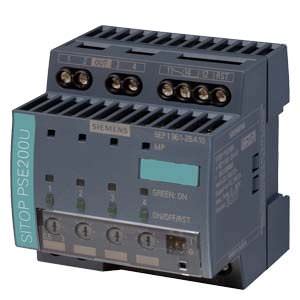
Selectivity module Siemens
Область применения
The selectivity module is used in conjunction with 24 V power supplies to distribute the load current over several feeders and to monitor the individual currents. Faults in individual circuits caused by overload or short-circuit are detected and selectively switched off so that further load current paths remain unaffected by the fault. This achieves fast fault diagnostics and minimizes downtimes.

Обзор
Selectivity and rapid fault localization in 24 V feeders
The SITOP PSE200U and SITOP select selectivity modules are the optimal expansion for all 24 V power supplies to distribute the load current to several feeders and to monitor it. Overload and short-circuit in one or more feeders is reliably detected and signaled.
The electronics permit brief current peaks caused, for example, by high inrush currents, but disconnects feeders in the event of an extended overload. This is ensured even on high-resistance lines and in the case of "creeping" short-circuits. In such cases, miniature circuit breakers fail to trip, or trip too late, even if the power supply unit could deliver the required tripping current. The SITOP expansion module continues to supply the intact feeders with 24 V absolutely free of interruptions and feedback – a feature which avoids a possible total system failure.
Дизайн
The selectivity module is specially designed for the response of switched-mode power supply units and the 24 V DC feeders to be supplied. Individual setting of the current allows optimum adaptation to the respective feeder.
Функции
Monitoring
The current per output is monitored by the selectivity modules; if the set threshold of the output is
exceeded, the output is
switched off according to a predefined time-current characteristic curve. In addition, the supplying 24 V input voltage is constantly being monitored. As soon as this voltage threatens to fail, the path with a higher current than the set threshold is
disconnected immediately. All other feeders continue to be supplied without interruption.
Signaling
Signaling of the faulty feeder takes place by the LEDs on the device as well as via group signaling contact or single-channel signaling. The selectivity module with single-channel signaling outputs the status of the 4 outputs cyclically by means of a serial code which can be read in by a digital PLC input.
Free function blocks for SIMATIC S7-300/400/1200/1500 for STEP 7 and TIA Portal as well as SIMOTION CPUs with SIMOTION SCOUT are available for evaluation. This enables simple integration into the S7 diagnostics and host control or HMI systems.
More information, as well as the function blocks for download, can be found at:
SIMATIC S7:
http://support.automation.siemens.com/WW/view/en/61450284
SIMOTION:
http://support.automation.siemens.com/WW/view/en/82555461
Connection and disconnection of the outputs
During device startup you can select between simultaneous connection of all outputs as well as sequential connection or load-dependent connection of the outputs (to reduce the peak inrush currents).
Each output can be manually connected and disconnected on the device (for example, for commissioning or service). Disconnected outputs can be connected by means of remote reset (24 V input). Prerequisite is that the outputs were not disconnected manually on the device.
Особенности
- Reliable shutdown in case of overload regardless of cable lengths or cable cross-sections
- 4 load feeders per module with individually adjustable maximum current for each output
- Two versions for remote diagnostics: Group signaling contact or single-channel signaling
- Evaluation via free-of-charge SIMATIC S7 function blocks (S7-1500/1200/300/400) for modules with single-channel signaling (PSE200U)
- LEDs for rapid on-site fault localization
- Remote reset possible from a central location (PSE200U)
- Simple commissioning thanks to manual switch on/off of outputs (PSE200U)
- Sequential connection of feeders to reduce total inrush current
- Sealable transparent cover over adjusters for currents and times protects against maladjustment (PSE200U)
Технические данные
Order number | 6EP1961-2BA11 | 6EP1961-2BA31 | 6EP1961-2BA21 | 6EP1961-2BA41 | 6EP1961-2BA00 | |
|---|---|---|---|---|---|---|
product brand name | SITOP PSE200U | SITOP PSE200U | SITOP PSE200U | SITOP PSE200U | SITOP select | |
Type of current supply | Selectivity module, 4 x 3 A Common signal contact | Selectivity module, 4 x 3 A Single-channel signaling | Selectivity module, 4 x 10 A Common signal contact | Selectivity module, 4 x 10 A Single-channel signaling | Diagnosis module, 4 x 10 A | |
Input |
|
|
|
|
| |
Type of the power supply network | Controlled DC voltage | Controlled DC voltage | Controlled DC voltage | Controlled DC voltage | Controlled DC voltage (SITOP select is not designed for operation with DC UPS module 40 A (6EP1 931-2FC21/-2FC42) | |
Supply voltage for DC Rated value | 24 V | 24 V | 24 V | 24 V | 24 V | |
Input voltage for DC | 22 ... 30 V | 22 ... 30 V | 22 ... 30 V | 22 ... 30 V | 22 ... 30 V | |
Overvoltage overload capability | 35 V | 35 V | 35 V | 35 V | 35 V; 100 ms | |
Input current at rated input voltage 24 V Rated value | 12 A | 12 A | 40 A | 40 A | 40 A | |
Output |
|
|
|
|
| |
Voltage curve at output | controlled DC voltage | controlled DC voltage | controlled DC voltage | controlled DC voltage | controlled DC voltage | |
Formula for output voltage | Vin - approx. 0.2 V | Vin - approx. 0.2 V | Vin - approx. 0.2 V | Vin - approx. 0.2 V | Vin - approx. 0.3 V | |
Relative overall tolerance of the voltage Note | In accordance with the supplying input voltage | In accordance with the supplying input voltage | In accordance with the supplying input voltage | In accordance with the supplying input voltage | In accordance with the supplying input voltage | |
Number of outputs | 4 | 4 | 4 | 4 | 4 | |
Output current up to 60 °C per output Rated value | 3 A | 3 A | 10 A | 10 A | 10 A | |
Adjustable response value current of the current-dependent overload release | 0.5 ... 3 A | 0.5 ... 3 A | 3 ... 10 A | 3 ... 10 A | 2 ... 10 A | |
Type of response value setting | via potentiometer | via potentiometer | via potentiometer | via potentiometer | via potentiometer | |
Product property parallel switching of outputs | No | No | No | No | No | |
Type of outputs connection | Simultaneous connection of all outputs after power up of the supply voltage > 20 V, delay time of 25 ms, 100 ms or adjustable "load optimised" via DIP switch for sequential connection | Simultaneous connection of all outputs after power up of the supply voltage > 20 V, delay time of 25 ms, 100 ms or adjustable "load optimised" via DIP switch for sequential connection | Simultaneous connection of all outputs after power up of the supply voltage > 20 V, delay time of 25 ms, 100 ms or adjustable "load optimised" via DIP switch for sequential connection | Simultaneous connection of all outputs after power up of the supply voltage > 20 V, delay time of 25 ms, 100 ms or adjustable "load optimised" via DIP switch for sequential connection | Simultaneous connection of all outputs after power up of the supply voltage, delay time of 24 ms or 100 ms programmable for sequential connection | |
Efficiency |
|
|
|
|
| |
Efficiency in percent | 97 % | 97 % | 99 % | 99 % | 97 % | |
Active power loss at rated output current at rated output current typical | 9 W | 9 W | 10 W | 10 W | 30 W | |
Switch-off characteristic per output |
|
|
|
|
| |
Switching characteristic |
|
|
|
|
| |
| Iout = 1.0 ...1.5 x set value, switch-off after approx. 5 s | Iout = 1.0 ...1.5 x set value, switch-off after approx. 5 s | Iout = 1.0 ...1.5 x set value, switch-off after approx. 5 s | Iout = 1.0 ...1.5 x set value, switch-off after approx. 5 s | Iout = 1.0 ...1.3 x set value, switch-off after approx. 5 s | |
| Iout = 1.5 x set value, switch-off not before typ. 100 ms | Iout = 1.5 x set value, switch-off not before typ. 100 ms | Iout = 1.5 x set value, switch-off not before typ. 100 ms | Iout = 1.5 x set value, switch-off not before typ. 100 ms | Iout = 1.3 x set value, switch-off after approx. 50 ... 100 ms | |
| Iout > set value and Vin < 20 V, switch-off after approx. 0.5 ms | Iout > set value and Vin < 20 V, switch-off after approx. 0.5 ms | Iout > set value and Vin < 20 V, switch-off after approx. 0.5 ms | Iout > set value and Vin < 20 V, switch-off after approx. 0.5 ms | Iout > set value and Vin < 20 V, switch-off after approx. 0.5 ms | |
Residual current at switch-off typical | 20 mA | |||||
Design of the reset device/resetting mechanism | via sensor per output | via sensor per output | via sensor per output | via sensor per output | Using keys on the module | |
Remote reset function | Non-electrically isolated 24 V input (signal level "high" at > 15 V) | Non-electrically isolated 24 V input (signal level "high" at > 15 V) | Non-electrically isolated 24 V input (signal level "high" at > 15 V) | Non-electrically isolated 24 V input (signal level "high" at > 15 V) | - | |
Protection and monitoring |
|
|
|
|
| |
Overload protection type for cables | 5 A per output (not accessible) | 5 A per output (not accessible) | 15 A per output (not accessible) | 15 A per output (not accessible) | blade-type fuse per output (equipped with 15 A fuse in as-delivered state) | |
Display version for normal operation | Three-color LED per output: green LED for "Output switched through"; yellow LED for "Output switched off manually"; red LED for "Output switched off due to overcurrent" | Three-color LED per output: green LED for "Output switched through"; yellow LED for "Output switched off manually"; red LED for "Output switched off due to overcurrent" | Three-color LED per output: green LED for "Output switched through"; yellow LED for "Output switched off manually"; red LED for "Output switched off due to overcurrent" | Three-color LED per output: green LED for "Output switched through"; yellow LED for "Output switched off manually"; red LED for "Output switched off due to overcurrent" | Two-color LED per output: green LED for "Output switched through"; red LED for "Output switched off due to overcurrent" | |
Design of the switching contact for signaling function | Common signal contact (changeover contact, rating 0.1 A/24 V DC) | Status signal output (pulse/pause signal, can be evaluated via Simatic function block) | Common signal contact (changeover contact, rating 0.1 A/24 V DC) | Status signal output (pulse/pause signal, can be evaluated via Simatic function block) | Common signal contact (NO contact, rating 0.5 A/24 V DC) | |
Safety |
|
|
|
|
| |
Galvanic isolation between input and output at switch-off | No | No | No | No | No | |
Operating resource protection class | Class III | Class III | Class III | Class III | Class III | |
Certificate of suitability |
|
|
|
|
| |
| Yes | Yes | Yes | Yes | Yes | |
| Yes | Yes | Yes | Yes | Yes | |
| UL-Recognized (UL 2367) File E328600; cULus-Listed (UL 508, CSA C22.2 No. 107.1) File E197259 | UL-Recognized (UL 2367) File E328600; cULus-Listed (UL 508, CSA C22.2 No. 107.1) File E197259 | UL-Recognized (UL 2367) File E328600; cULus-Listed (UL 508, CSA C22.2 No. 107.1) File E197259 | UL-Recognized (UL 2367) File E328600; cULus-Listed (UL 508, CSA C22.2 No. 107.1) File E197259 | UL-Recognized (UL 2367) File E328600; cULus-Listed (UL 508, CSA C22.2 No. 107.1) File E197259; cURus (UL 60950, CSA C22.2 No. 60950) File E151273 | |
Standard |
|
|
|
|
| |
| according to EN 60950-1 and EN 50178 | according to EN 60950-1 and EN 50178 | according to EN 60950-1 and EN 50178 | according to EN 60950-1 and EN 50178 | according to EN 60950-1 and EN 50178 | |
| IECEx (IEC 60079-0, -15); ATEX (EN 60079-0, -15); cCSAus (CSA C22.2 No. 213, No. 60079, ANSI/ISA 12.12.01, UL 60079) | IECEx (IEC 60079-0, -15); ATEX (EN 60079-0, -15); cCSAus (CSA C22.2 No. 213, No. 60079, ANSI/ISA 12.12.01, UL 60079) | IECEx (IEC 60079-0, -15); ATEX (EN 60079-0, -15); cCSAus (CSA C22.2 No. 213, No. 60079, ANSI/ISA 12.12.01, UL 60079) | IECEx (IEC 60079-0, -15); ATEX (EN 60079-0, -15); cCSAus (CSA C22.2 No. 213, No. 60079, ANSI/ISA 12.12.01, UL 60079) | ATEX (EN 60079-0, -15); cCSAus (CSA E60079-0, -15; UL 60079-0, -15; UL 1604) | |
Certificate of suitability |
|
|
|
|
| |
| IECEx Ex nA nC IIC T4 Gc; ATEX (EX) II 3G Ex nA nC IIC T4 Gc; cCSAus Class I, Div. 2, Group ABCD, T4 | IECEx Ex nA IIC T4 Gc; ATEX (EX) II 3G Ex nA IIC T4 Gc; cCSAus Class I, Div. 2, Group ABCD, T4 | IECEx Ex nA nC IIC T4 Gc; ATEX (EX) II 3G Ex nA nC IIC T4 Gc; cCSAus Class I, Div. 2, Group ABCD, T4 | IECEx Ex nA IIC T4 Gc; ATEX (EX) II 3G Ex nA IIC T4 Gc; cCSAus Class I, Div. 2, Group ABCD, T4 | ATEX (EX) II 3G Ex nAC IIC T4 U; cCSAus Class I, Div. 2, Group ABCD, T4 | |
| Yes | Yes | Yes | Yes | No | |
Shipbuilding approval | GL, ABS | GL, ABS | GL, ABS | GL, ABS | ||
Protection class IP | IP20 | IP20 | IP20 | IP20 | IP20 | |
EMC |
|
|
|
|
| |
Standard |
|
|
|
|
| |
| EN 55022 Class B | EN 55022 Class B | EN 55022 Class B | EN 55022 Class B | EN 55022 Class B | |
| EN 61000-6-2 | EN 61000-6-2 | EN 61000-6-2 | EN 61000-6-2 | EN 61000-6-2 | |
Operating data |
|
|
|
|
| |
Ambient temperature |
|
|
|
|
| |
| 0 ... 60 °C | 0 ... 60 °C | 0 ... 60 °C | 0 ... 60 °C | 0 ... 60 °C | |
| with natural convection | with natural convection | with natural convection | with natural convection | with natural convection | |
| -40 ... +85 °C | -40 ... +85 °C | -40 ... +85 °C | -40 ... +85 °C | -40 ... +85 °C | |
| -40 ... +85 °C | -40 ... +85 °C | -40 ... +85 °C | -40 ... +85 °C | -40 ... +85 °C | |
Mechanics |
|
|
|
|
| |
Type of electrical connection | screw-type terminals | screw-type terminals | screw-type terminals | screw-type terminals | screw-type terminals | |
| +24 V: 2 screw terminals for 0.5 ... 10 mm²; 0 V: 2 screw terminals for 0.5 ... 4 mm² | +24 V: 2 screw terminals for 0.5 ... 10 mm²; 0 V: 2 screw terminals for 0.5 ... 4 mm² | +24 V: 2 screw terminals for 0.5 ... 10 mm²; 0 V: 2 screw terminals for 0.5 ... 4 mm² | +24 V: 2 screw terminals for 0.5 ... 10 mm²; 0 V: 2 screw terminals for 0.5 ... 4 mm² | +24 V: 2 screw terminals for 0.33 ... 10 mm²; 0 V: 2 screw terminals for 0.22 ... 4 mm² | |
| Output 1 ... 4: 1 screw terminal each for 0.5 ... 4 mm² | Output 1 ... 4: 1 screw terminal each for 0.5 ... 4 mm² | Output 1 ... 4: 1 screw terminal each for 0.5 ... 4 mm² | Output 1 ... 4: 1 screw terminal each for 0.5 ... 4 mm² | Output 1 ... 4: 1 screw terminal each for 0.22 ... 4 mm² | |
| 3 screw terminals for 0.5 ... 4 mm² | 3 screw terminals for 0.5 ... 4 mm² | 3 screw Запрос коммерческого предложения× Сообщение отправлено× В ближайшее время сообщение будет обработано. Письмо с номером обращения отправлено на Ваш почтовый ящик. Спасибо за то, что выбрали Первый ZIP! Что-то пошло не так...× К сожалению, наша система расценила Ваше сообщение как спам. Если это произошло по ошибке, пожалуйста, обратитесь к нам по электронной почте. Приносим извинения за возможные неудобства.  Вы отправляете нам запрос  Если у нас есть прайс-лист, мы отправляем Вам ответ в течение дня. А если у нас нет прайс-листа по запрошенным товарам?     Если у нас нет прайс-листа, мы отправляем запрос производителю.  Ответ от производителя может занять до 5 дней и более. Ответ от производителя может занять до 5 дней и более.  Запрос производителю мы отправляем только для конечных потребителей.  Торгующим организациям коммерческие предложения предоставляются только по прайсовым позициям: Siemens Beckhoff Pepperl+Fuchs Phoenix Contact PILZ Turck Leuze Electronic Endress+Hauser Murr Elektronik Schmersal | |||