Модули DC-UPS со встроенными конденсаторами Siemens

Область применения
The high-capacitance double-layer capacitors bridge power failures for a few minutes. The time is normally sufficient, for example, for the safe shutdown of PC-based automation systems. The USB interface and a free software tool enable easy communication with the PC.
The capacitors have an extremely long life even at high temperature, and can be used at ambient temperatures of up to 60 °C. SITOP UPS500P in IP65 degree of protection can also be installed outside the control cabinet in a distributed configuration.

Configuration with SITOP UPS500S:
24 V buffering for backing up process data and performing a controlled shutdown of a PC. To relieve the load on the UPS, the actuators are supplied directly from the power supply unit.
Обзор
SITOP 24V power supplies can be expanded with a SITOP UPS500 uninterruptible DC power supply (DC UPS) for bridging short-term power failures in the order of minutes. For PC-based automation solutions, the high-capacity double-layer capacitors of the SITOP UPS500 supply enough energy to back up the operation and application data and to shut down software applications in a defined manner. You can increase the buffer times using SITOP PSU501S expansion modules (up to 3).
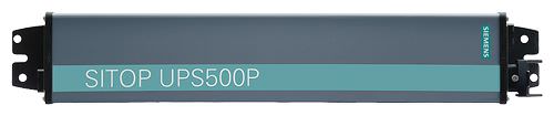
The IP65 version SITOP UPS500P in long metal housing is ideally suited to distributed use.
Дизайн
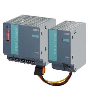
SITOP UPS500S
- Compact 24 V/ 15 A basic units with integrated energy storage units of 2.5 or 5 kW
- Digital inputs/outputs and USB interface
- For combination with up to three UPS501S expansion modules
(5 kW each) to extend the buffering time - Metal housing in IP20 degree of protection for mounting on standard rails

SITOP UPS501S expansion module
- Additional energy storage (5 kW)
- Up to 3 expansion modules can be connected to a SITOP UPS500S to extend the buffer times
- Can be easily connected to SITOP UPS500S via a user-friendly plug-in system
- Complete with balancing and safety circuits
SITOP UPS500P
- 24 V/ 7 A basic units with integrated energy storage units of 5 or 10 kW
- USB interface
- Rugged aluminum housing in IP65 degree of protection for distributed applications
- Screw mounting in all mounting positions
Функции
SITOP DC UPS software tool
Via the USB interface, all relevant messages about the status of the uninterruptible DC power supply can be transmitted to a PC (e.g. SIMATIC IPC). The DC UPS can also be configured via the USB interface.
The SITOP DC UPS software provides the user with a free tool that is extremely easy to use for the purpose of monitoring and configuring the DC UPS. Signals sent from the uninterruptible DC power supply can be processed on the PC. In monitoring mode, the statuses of the uninterruptible DC power supply are visualized on the PC.
Safe shutdown in the event of a power failure and automatic PC restart are supported. It is also possible to freely define responses to the different operating states of the uninterruptible DC power supply, so that extremely flexible integration into a wide variety of applications is possible.
Overview of configuration possibilities:
- Times for shutting down the PC
- UPS switch-off
- Further processing of all signals, e.g. linking to proprietary software or WinCC flexible
- Monitoring and display of UPS operating status
- OPC server for linking signals to proprietary applications
- Automatic restarting of IPCs when power is restored during shutdown
The software runs under the operating systems Windows 2000, Windows XP, Windows Vista and Windows 7. Free download from:
http://support.automation.siemens.com/WW/view/en/48946053

Monitoring and configuration window of software V3 for SITOP DC UPS
Особенности
- 24 V buffering for a few minutes to allow data to be backed up and applications to be closed.
- Absolutely maintenance-free
- Long lifetime, even at high temperatures
- High ambient temperatures up to +60 °C
- Short charging times
- No ventilation is required since no gas is emitted
- Distributed applications possible without control cabinet
- Software tool, free of charge, for easy configuring and integrating in PC-based systems
Технические данные
The UPS500S can be extended to 20 kW using UPS501S expansion modules to extend the buffering time. The table shows the maximum buffering time for the possible configurations and the two UPS500P units for different load currents.
The load current can be set to 1 A or 2 A with the UPS500S.
Selection table SITOP UPS500 (optional with SITOP UPS501S expansion module) and mains buffering times
Buffering and charging times | ||||||||||
SITOP UPS500S/501S configurations | UPS500P | |||||||||
Basic unit | 2.5 kW | 5 kW | 2.5 kW | 5 kW | 2.5 kW | 5 kW | 2.5 kW | 5 kW | 5 kW | 10 kW |
Expansion modules | - | - | 1 × 5 kW | 1 × 5 kW | 2 × 5 kW | 2 × 5 kW | 3 × 5 kW | 3 × 5 kW | - | - |
Total energy | 2.5 kW | 5 kW | 7.5 kW | 10 kW | 12.5 kW | 15 kW | 17.5 kW | 20 kW | 5 kW | 10 kW |
Load current | Buffer times | |||||||||
0.5 A | 134 s | 236 s | 390 s | 478 s | 632 s | 748 s | 851 s | 1007 s | 284 s | 647 s |
0.8 A | 90 s | 167 s | 266 s | 346 s | 440 s | 527 s | 580 s | 706 s | 190 s | 435 s |
1 A | 75 s | 138 s | 219 s | 296 s | 365 s | 414 s | 490 s | 572 s | 153 s | 351 s |
2 A | 38 s | 76 s | 122 s | 156 s | 203 s | 230 s | 265 s | 306 s | 80 s | 152 s |
3 A | 26 s | 52 s | 82 s | 106 s | 136 s | 159 s | 186 s | 213 s | 53 s | 108 s |
4 A | 19 s | 39 s | 61 s | 81 s | 101 s | 120 s | 139 s | 160 s | 40 s | 84 s |
5 A | 15 s | 31 s | 49 s | 65 s | 81 s | 95 s | 111 s | 130 s | 30 s | 68 s |
6 A | 12 s | 26 s | 40 s | 55 s | 67 s | 80 s | 94 s | 106 s | 25 s | 57 s |
7 A | 10 s | 21 s | 34 s | 47 s | 58 s | 69 s | 81 s | 82 s | 21 s | 49 s |
8 A | 8 s | 18 s | 29 s | 40 s | 50 s | 59 s | 69 s | 79 s | - | - |
10 A | 6 s | 15 s | 23 s | 32 s | 39 s | 47 s | 54 s | 62 s | - | - |
12 A | 4 s | 12 s | 19 s | 26 s | 32 s | 38 s | 44 s | 52 s | - | - |
15 A | 3 s | 9 s | 14 s | 20 s | 25 s | 30 s | 35 s | 40 s | - | - |
Charing current | Charging times | |||||||||
2 A | 54 s | 120 s | 158 s | 223 s | 263 s | 318 s | 355 s | 417 s | 130 s | 360 s |
1 A | 110 s | 205 s | 311 s | 425 s | 503 s | 625 s | 695 s | 816 s | - | - |
Important information for selecting the energy storage units:
When the mains buffering times were determined, the discharge period of new or non-aged, completely charged capacitors was used as a basis. At a continuous ambient temperature of +50 °C, a loss of capacity of approx. 20% must be considered after a service life of 8 years.
Product | SITOP UPS500S 15 A | SITOP UPS500P 7 A |
Power supply, type | Basic unit 15 A | Basic unit 7 A, IP65 |
Article No. | 6EP1933-2EC41 (with USB interface and 2.5 kW) | 6EP1933-2NC01 (with USB interface and 5 kW) |
Input "In L+ / In M" for normal operation | Controlled DC voltage | Controlled DC voltage |
Rated voltage Uinrated1) | 24 V DC | 24 V DC |
Voltage range | 22 ... 29 V | 22.5 ... 29 V |
Connection threshold for buffering | 22 ... 25.5 V DC in 0.5 V increments, adjustable | 22.5 V DC ±0.1 V |
Rated current Iin rated | 15.2 A + approx. 2.3 A with empty energy storage (capacitor) | 7 A + approx. 2 A with empty energy storage (capacitor) |
Mains buffering | ||
Mains buffering or buffering times without add-on modules | 6EP1933-2EC41: 15 A for 3 s or 10 A for 6 s or 5 A for 15 s or 2 A for 38 s | 7 A for 49 s or 5 A for 68 s or 3 A for 108 s or 1 A for 351 s |
Mains buffering or buffering times with expansion modules | For longer buffering times, see table | - |
On/off control circuit | External isolated NO contact (loading max. 15 V DC/max. 10 mA) is required; opening the control circuit terminates buffer mode. | - |
Methods of setting the buffering time | Adjustable using DIP switches to a maximum buffering time up to forced shutdown at approx. 7 V internal capacitor voltage (output remains constant at 24 V up to that point) or to a time limit of 5 ... 315 s (in 10 s increments) if the energy content is sufficient for the required current | - |
Interruption | Adjustable with DIP switch, either:
or
| - |
Output "Out L+ / Out M" for normal operation | ||
Rated voltage Uoutrated | 24 V DC | 24 V DC |
Voltage range | 23.3 ... 24.7 V DC or 24 V DC ± 3% | 23.3 ... 24.7 V DC or 24 V DC ± 3% |
Startup delay | approx. 600 ms | approx. 600 ms |
Voltage rise | ca. 25 ms | ca. 25 ms |
Output current Iout | 0 ... 15 A | 0 ... 7 A |
Dynamic current with overload | Electronic current limitation to typically 25 A for approx. 200 ms, then electronic shutdown of the output with automatic restart attempts (approx. 20 s intervals between restart attempts) | Electronic shutdown at typ. 30 A, automatic restart after 20 s |
Dynamic current with short-circuit | Electronic current limitation to typically 25 A for approx. 110 ms, then electronic shutdown of the output with automatic restart attempts (approx. 20 s intervals between restart attempts) | Electronic shutdown at typ. 30 A, automatic restart after 20 s |
Output "Out L+ / Out M" for buffer mode | ||
Rated voltage Uoutrated | 24 V DC | 24 V DC |
Approximate voltage range | 23.3 ... 24.7 V DC or 24 V DC ± 3% | 23.3 ... 24.7 V DC or 24 V DC ± 3% |
Output current Iout | 0 ... 15 A | 0 ... 7 A |
Dynamic current with overload | Electronic current limitation to typically. 25 A for approx. 200 ms, then electronic shutdown of the output (restart following return to normal operation) | Electronic shutdown at typ. 30 A, automatic restart after 20 s |
Dynamic current with short-circuit | Electronic current limitation to typically. 25 A for approx. 110 ms, then electronic shutdown of the output (restart following return to normal operation) | Electronic shutdown at typ. 30 A, automatic restart after 20 s |
Charging current | Approx. 1 A (factory setting), adjustable to 1 A or 2 A (charging is carried out with closed and open on/off circuit) | 2 A permanently set |
Charging time after a discharge | 6EP1933-2EC41: 110 s with 1 A, 54 s with 2 A | Approx. 300 s |
Charging time with add-on modules | For longer charging times, see table | Not applicable |
Efficiency / heat loss |
| |
At Uout rated, Iout rated approx. | 97.5 % / 9 W | 96.5 % / 5.2 W |
Protection and monitoring | ||
Reverse polarity protection | against polarity reversal on input voltage | against polarity reversal on input voltage |
Overload protection | Electronic shutdown of the output in accordance with "dynamic current with overload" in normal operation (automatic restart attempts) or in buffer mode (restart following return to normal operation) | Electronic shutdown of the output in accordance with "dynamic current with overload" in normal operation (automatic restart attempts) or in buffer mode (restart following return to normal operation) Thermal overload protection |
Short-circuit protection | Electronic shutdown of the output in accordance with "dynamic current with short-circuit" in normal operation (automatic restart attempts) or in buffer mode (restart following return to normal operation), built-in (inaccessible) 20 A fuse. | Electronic shutdown of the output in accordance with "dynamic current with overload" in normal operation (automatic restart attempts) or in buffer mode (restart following return to normal operation) Thermal overload protection |
Signaling |
| |
Normal operation | Green LED (OK) and isolated relay contact (changeover contact)2) | Green LED (OK ) |
Buffer mode (capacitor supplies load alone or in addition to the PS in the case of overload) | Green LED (Bat) and isolated relay contact (changeover contact) 2) | Yellow LED (Bat) |
Alarm (buffer not ready, or prewarning from < 12 V capacitor voltage) | Red LED (alarm) and isolated relay contact (changeover contact)2) | Red LED (Alarm) |
"Capacitor charge > 85 %" 3) | Second green LED (Bat > 85 %) and isolated NO contact closed (off position = open) | Second green LED (Bat > 85 %) |
USB port | Output of all alarm signals and receipt of the "Remote Timerstart" signal. Technical design: Specification 2.0 with full speed, i.e. 2 Mbps Supplied with +5 V ("self powered"). Required connection to the PC: Commercially available 4-core shielded cable, 90 ohms, max. 5 m, USB series "A" connector to PC and USB series "B" connector to DC UPS | Output of all alarm signals and receipt of the "Remote Timerstart" signal. Technical design: Specification 2.0 with full speed, i.e. 2 Mbps Supplied with +5 V ("self powered"). Required connection to the PC: see connector set |
Software | A software tool for reading and processing signals (runs under Windows 2000, Windows XP, Windows Vista and Windows 7) is available for download online at | A software tool for reading and processing signals (runs under Windows 2000, Windows XP, Windows Vista and Windows 7) is available for download online at |
Control signals | ||
On/off control signal | Buffering is terminated by opening the control circuit or by means of DIP switches on the device (DIP switch must be in "Off" position). All other functions are retained. | Not applicable |
"Remote Timerstart" via USB port | Starts mains buffering for the set buffering time | Starts mains buffering for the set buffering time |
Safety | ||
Primary/secondary isolation | No | No |
Protection class | Class III (ext. circuit and power supply unit: SELV in accordance with EN 60950 required) | Class III (ext. circuit and power supply unit: SELV in accordance with EN 60950 required) |
EMC | ||
Emitted interference | Radio interference suppression according to EN 55022, limit-value curve B | Radio interference suppression according to EN 55022, limit-value curve B |
Interference immunity | Interference immunity according to EN 61000-6-2 | Interference immunity according to EN 61000-6-2 |
Ambient conditions | ||
Ambient temperature in operation | 0 ... +60 °C with natural convection | 0 ... +55 °C with natural convection |
Transport/storage temperature | -40 ... +70 °C | -40 ... +70 °C |
Degree of protection (EN 60529) | IP20 | IP65 |
Humidity class | Rated conditions in accordance with EN 60721, climate class 3K3 (relative humidity 5% ... 85% and absolute humidity 1 g/m3 ... 25 g/m3; no condensation) | Rated conditions in accordance with EN 60721, climate class 3K3 (relative humidity 5% ... 85% and absolute humidity 1 g/m3 ... 25 g/m3; no condensation) |
Approvals | ||
CE | Yes | Yes |
UL/cUL (CSA) approval | cULus-listed (UL 508, CSA C22.2 No. 107.1) File E197259 | - |
Mechanics | ||
Input connections 24 V DC | 2 screw terminals for 1 ... 4 mm2/17 ... 11 AWG | See connector set4) |
Output connections 24 V DC | 4 screw terminals for 1 ... 4 mm2/17 ... 11 AWG | See connector set4) |
Connections for control circuit and alarm signals | 10 screw terminals for 0.5 ... 2.5 mm2/20 ... 13 AWG | Not applicable |
USB port | Yes | Yes |
Dimensions (W x H x D) in mm | 120 x 125 x approx. 125 | 400 (without connector) x 80 x 80 |
Required clearances | 50 mm above and 50 mm below the device | 50 mm above and 50 mm below the device |
Weight | Approx. 1.0 kg | Approx. 1.9 kg |
Installation | Can be snapped onto standard mounting rail EN 60715 35x7.5/15 | Screw mounting |
1) All SITOP 24 V DC power supplies are permissible without restriction
2) Permissible contact rating: 60 V DC/1 A or 30 V AC/1 A.
3) 85% with regard to residual capacity still available depending on aging. The original capacity (= capacity when new) reduces by only approx. 20 % within 8 years of operation even at a high ambient temperature of the device of +50 °C, for example, so that 80 % residual capacity still remains. The backup times also reduce by approximately 20 % in 8 years (at +50 °C) with small currents (up to approximately 5 A), and by approximately 30 % with high load currents (over 10 A).
Note: The lower the ambient temperature, the smaller the capacity reduction (approximately one half per 10 °C lower ambient temperature, that is at +40 °C, for example, only 10 % capacity reduction in 8 years)
4) “The connector set contains connection plugs for input and output and pre-assembled USB cables 2 m long (connector set not included in the scope of delivery of SITOP UPS500P); MLFB: 6EP1975-2ES00
Product | SITOP UPS501S |
Power supply, type | Expansion module |
Article No. | 6EP1935-5PG01 |
Mechanics | |
Connections | Can be easily connected to SITOP UPS500S via a user-friendly plug-in system |
Dimensions (W x H x D) in mm | Approx. 70 x 125 x 125 |
Weight | Approx. 0.7 kg |
Installation | Can be snapped onto standard mounting rail EN 60715 35x7.5/15 |
Дополнительно
Connector set for UPS500P | 6EP1975-2ES00 |
consisting of connector for input and output with pre-assembled USB cable (2 m long) |
Дальнейшая информация
The SITOP Selection Tool offers detailed selection guidance according to criteria such as the required backup time, nominal current or peak current. Available at:
http://www.siemens.com/sitop-selection-tool


 Ответ от производителя может занять до 5 дней и более.

