LOHER DYNAVERT T PWM Inverters Siemens
Область применения
Typical applications
- Power stations and utilities
- Plastic industry
- Basic materials industry
- Test stands
- Conveyor technology
- Applications in general machinery construction
Обзор
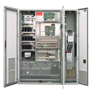
LOHER DYNAVERT T PWM Inverters
General description
LOHER DYNAVERT T can be flexibly integrated into any automation concept – whether using conventional control technology or bus systems.
LOHER DYNAVERT T can be connected to any of the normally encountered line supply voltages – and can feed both synchronous and asynchronous motors. All of the drive requirements are taken into consideration from the word go – from the coupling, through the motor, cables, drive inverter, line supply situation and connection to the supervisory control system.
Features
Explosion protection
- ATEX‑certified for motors located in hazardous zones
- A main contactor is not required
Safe Torque Off
- The Safe Torque Off function prevents unexpected starting in compliance with EN 60204‑1, implemented according to EN 954‑1, Category 3
Power unit
- This corresponds to the EMC Directives (EN 61800-3 environment 2) as a result of the line filter integrated as standard·
- Low harmonics fed back into the line supply as a result of the integrated line reactor
- Output filter to permit longer motor cables
- Insulation monitoring for IT line supplies for 500/690 V drive units as well as ground fault monitoring for TN and TT line supplies integrated in the 400 V drive units
- Wide supply voltage range
- Low motor noise and low drive inverter and motor losses as a result of the optimized pulse pattern
- Normal fuses can be used for protection (gL characteristic)
Control section
- High level of personnel and plant protection through protective separation between the analog and digital control peripheral and the power unit according to VDE 0106/EN 50178
Operator control and setting
- Transparent operator control and setting using a menu-prompted 4-line plain text display with membrane keypad at the drive inverter – or up to 1,000 m away in the main control room via RS485
- Extensive functions using the Windowsbased PC operator control program
Communication
- Communication via a conventional terminal strip with freely‑programmable digital and analog inputs/outputs, with
- parameterizable limit value signals
- parameterizable timers
- parameterizable damping elements
- parameterizable drive inverter behavior when inputs/outputs respond
- Communication and parameterization via
- PC using IMS (Inverter Management Software) via RS232/RS485
- external operator panel via RS485
- bus systems such as PROFIBUS DP or Modbus RTU
Drive behavior for LOHER DYNAVERT T
- Synchronous and asynchronous motors can be controlled
- Two closed‑loop control types for induction motors:
- field‑oriented control for applications demanding a high dynamic performance
- space‑vector control for standard applications (without feedback)
- Optimum braking without supplementary equipment using super‑saturation control
The following generally apply
- Automatic slip compensation
- Stall protection using current limiting control
- Flying restart circuit to connect to a rotating motor
- Automatic adaptation of the overload times
- Parameterizable DC braking for precise braking down to standstill
- Closed‑loop torque control
Особенности
Customer benefits
- Cabinet units and cabinet systems in IP21 or higher degrees of protection
- All of the drive units have their own connection space
- Compact dimensions
- Equipped with radio interference suppression
- Low harmonics fed back into the line supply
- Long motor cables can be used as a result of the integrated dv/dt filter
- Wide supply voltage range
- A main contactor is not required
- Drive units with 500 V and 690 V rated line supply voltage can be connected to non‑grounded line supplies (IT line supplies)
- ATEX‑certified motors for hazardous zones
Технические данные
Technical data overview
Rated input voltage | Typ. motor rated power compact units | Typ. motor rated power cabinet units/cabinet systems |
|---|---|---|
400 V | 2.2 ... 160 kW | 2.2 ... 630 kW |
500 V | 2.2 ... 200 kW | 2.2 ... 800 kW |
690 V | 7.5 ... 200 kW | 7.5 ... 6000 kW |
Brief overview | |
|---|---|
Line supply voltage | 3 ~ AC 230 ... 500 V (for TN/TT line supplies) |
Line supply cos φ (1) | approx. 0.99 |
Line supply frequency | 47 ... 63 Hz |
Maximum output frequency | 120 ... 250 Hz (Setting range depends on the unit power rating) |
Output voltage (basic fundamental) | 3 × 0 ... line supply voltage |
Clock frequency | 1.5 ... 10 kHz, can be parameterized (Setting range depends on the unit power rating) |
Motor cable length | 200 ... 300 m (690 V: 100 to 300 m) |
Degree of protection: | |


 Ответ от производителя может занять до 5 дней и более.

