SIPLUS HCS716I heating control systems Siemens
Область применения
The SIPLUS HCS716I heater control system is used, for example, to switch the small and medium output heat emitter arrays in thermoforming machines, drying ovens and packaging machines.
The SIPLUS HCS716I is a distributed I/O unit (slave) that communicates over the PROFIBUS DP fieldbus with a higher-level control system (master) such as SIMATIC S7/SIMOTION.
Обзор
The SIPLUS HCS716I heater control system was developed as a cost-optimized controller of heat emitter arrays in thermoforming machines. It is suitable for all generally available radiation devices such as quartz, quartz material, ceramic, halogen and infrared radiation devices.
SIPLUS HCS716I can be used wherever low-cost, resistive loads of small to medium output require switching in an industrial environment.
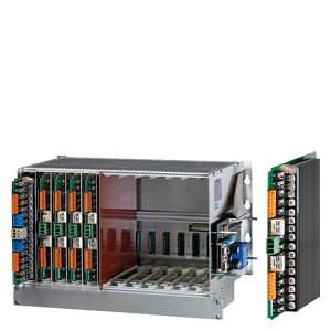
The SIPLUS HCS716I family comprises four racks and three power output modules.
HCS716I heater controller
Дизайн
The main components of the SIPLUS HCS716I heater control system are:
- 19" rack with bus board for inserting up to 4 or up to 12 power output modules, as well as a control module and CPU module
- Power output modules in double-height Eurocard format with 8/16 output channels
- Fan units with one or three fans (option)
- Communication over PROFIBUS DP, e.g. with SIMOTION, SIMATIC S7, or industrial PC
- Plug-in card system on the front
Интеграция
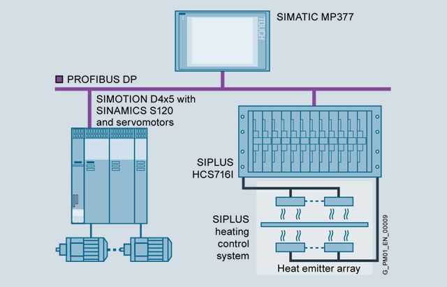
Example of application with SIMOTION, SINAMICS and HCS716I
Особенности
- High degree of modularity in terms of number of channels and channel performance
Технические данные
|
| ||||||||
Typ |
| 6BK1700-2AA00-0AA1 | 6BK1700-2AA10-0AA1 | 6BK1700-2AA70-0AA0 | 6BK1700-2AA80-0AA0 | 6BK1700-3AA00-0AA0 | 6BK1700-2BA70-0AA1 | 6BK1700-4BA80-0AA0 | 6BK1700-4CA00-0AA0 |
Produkt-Bezeichnung |
| HCS716I BGT Schwenkrahmen | HCS716I BGT Aufbaurahmen mit Flansch | HCS716I BGT Aufbaurahmen ohne Flansch | HCS716I BGT Aufbaurahmen schmale Version | HCS716I BGT Erweiterungsrahmen | HCS716I Leistungsbaugruppe LA716 | HCS716I Leistungsbaugruppe LA716I | HCS716I Leistungsbaugruppe LA716I HP |
Approbationen / Zertifikate |
| ||||||||
Eignungsnachweis |
| CE, KCC |
|
|
|
|
|
|
|
Versorgungsspannung |
| ||||||||
Spannungsart der Versorgungsspannung |
| AC |
|
|
|
|
|
|
|
Versorgungsspannung bei AC Bemessungswert | V | 230 |
|
|
| -- | 230 |
|
|
| % | 18 |
|
|
|
|
|
|
|
| % | 15 |
|
|
|
|
|
|
|
Versorgungsspannungsfrequenz |
|
| |||||||
| Hz | 50 |
|
|
|
|
|
|
|
| Hz | 60 |
|
|
|
|
|
|
|
| % | 5 |
|
|
|
|
|
|
|
Kommunikation |
| ||||||||
Ausführung der Schnittstelle |
| PROFIBUS DP |
|
|
|
| Systemschnittstelle |
|
|
Mechanische Merkmale |
| ||||||||
Einbaulage |
| waagerecht |
|
|
|
| senkrecht |
|
|
Befestigungsart |
| in einem Schwenkrahmen | Rückwand Schaltschrank |
|
|
| Befestigungsclip im Baugruppenträger |
|
|
Art der Lüftung |
| Eigen- oder Fremdbelüftung |
|
|
|
|
|
|
|
Schockfestigkeit gemäß IEC 60068-2-27 |
| 15g / 11 ms / 3 Schocks / Achse |
|
|
|
|
|
|
|
Schwingfestigkeit |
|
| |||||||
|
| 10 ... 58 Hz / 0,15 mm, 58 ... 150 Hz / 1g |
|
|
|
|
|
|
|
|
| 5 ... 9 Hz / 3,5 mm, 9 ... 500 Hz / 1g |
|
|
|
|
|
|
|
Schutzart IP |
| IP00 |
|
|
|
|
|
|
|
Abmessungen |
| ||||||||
| mm | 483 | 510 |
| 202,7 |
| 31 |
|
|
| mm | 265,5 | 310 |
| 309,5 |
| 233,4 |
|
|
| mm | 350 | 330 |
| 287 |
| 241 | 279 |
|
Elektromagnetische Verträglichkeit |
| ||||||||
leitungsgebundene Störeinkopplung BURST gemäß IEC 61000-4-4 |
| 2 kV Spannungsversorgungsleitungen / 2 kV Signalleitungen |
|
|
|
|
|
|
|
leitungsgebundene Störeinkopplung SURGE gemäß IEC 61000-4-5 |
| auf Versorgungsleitungen: 1 kV symmetrisch, 2 kV unsymmetrisch, PROFIBUS-Leitung unsymmetrisch 1 kV |
|
|
| keine zutreffenden Leitungen | auf Netzversorgungs- und Signalleitungen: 1 kV symmetrisch, 2 kV unsymmetrisch |
|
|
leitungsgebundene Störeinkopplung als Hochfrequenzeinstrahlung gemäß IEC 61000-4-6 |
| 10 V im Frequenzbereich 0,15 ... 80 MHz, Modulation 80 % AM mit 1 kHz, Bewertungskriterium A |
|
|
|
| 10 V (0,15 ... 80 MHz) |
|
|
elektrostatische Entladung gemäß IEC 61000-4-2 |
| 4 kV Kontaktentladung / 8 kV Luftentladung |
|
|
|
|
|
|
|
feldgebundene Störeinkopplung gemäß IEC 61000-4-3 |
| 10 V/m (80 ... 1 000 MHz), 3 V/m (1,4 ... 2,0 GHz), 1 V/m (2,0 ... 2,7 GHz) |
|
|
|
|
|
|
|
EMV-Störaussendung |
| nach EN 61000-6-4:2007 + A1:2011 |
|
|
|
|
|
|
|
Überspannungskategorie |
| III |
|
|
|
|
|
|
|
Klimatische Umgebungsbedingungen |
| ||||||||
Umgebungstemperatur |
|
| |||||||
| °C | 0 … 55 |
|
|
|
|
|
|
|
| °C | -40 … +70 |
|
|
|
|
|
|
|
| °C | -40 … +70 |
|
|
|
|
|
|
|
Luftdruck |
|
| |||||||
| hPa | 860 … 1 080 |
|
|
|
|
|
|
|
| hPa | 660 … 1 080 |
|
|
|
|
|
|
|
relative Luftfeuchte |
|
| |||||||
|
|
| |||||||
| % | 95 |
|
|
|
|
|
|
|
Aufstellungshöhe bei Höhe über NN maximal | m | 2 000 |
|
|
|
|
|
|
|
Дальнейшая информация
For further product details, refer to the "SIPLUS HCS716l Heater Control System" Operating Instructions,
http://support.automation.siemens.com/WW/view/en/50695867.
For further information, go tohttp://www.siemens.com/siplus-hcs.


 Ответ от производителя может занять до 5 дней и более.

