SIPLUS HCS724I heating control systems Siemens
- Current measuring modules
- Fan modules
- Line-voltage sensing modules
- Central interface modules
- Power output modules
Область применения
The SIPLUS HCS724I heater control system is used, for example, to control heat emitter arrays in:
- thermoforming machines
- blow molding machines
- plastics welding machines
- drying ovens
Обзор
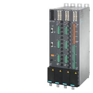
SIPLUS HCS724I heater controller
The SIPLUS HCS724I heater control system controls and switches heat emitter arrays and other resistive loads of medium to high output in the industrial environment.
The connection is made using PROFIBUS DP and provides, together with the SIMATIC S7, for example, a highly-modern and powerful automation system. As an option, a line-voltage sensing submodule can be integrated in order to compensate automatically and internally for variations in the line voltage.
Дизайн
The main components of the SIPLUS HCS724I heater control system are:
- Central interface module
- LA724I/LA724I HP/LA724I SSR power output modules: Up to 16 power output modules can be connected via the central interface module.
- Line-voltage sensing submodule (option)
- Fan module (option)
- Current measuring module (option)
- Communication over PROFIBUS DP, e.g. with SIMOTION, SIMATIC S7, or industrial PC
The central interface module and the LA724I/LA724I HP/LA724I SSR power output modules are installed in a metal enclosure and mounted on a plate in the control cabinet.
Customized, distributed solutions are also possible.
Интеграция
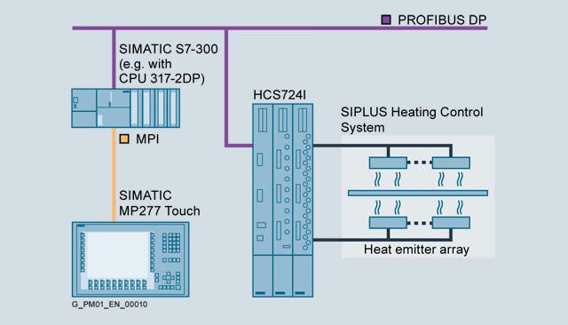
Application example with SIMOTION, SINAMICS, and SIPLUS HCS724I
Особенности
- Time is saved due to easy adaptation to the production process
- Excellent product quality thanks to integrated line voltage compensation
Технические данные
Order number |
| 6BK1700-2BA30-0AA0 | 6BK1700-2BA00-0AA0 | 6BK1700-4BA70-0AA0 | 6BK1700-2BA10-0AA0 | 6ES7171-1XX00-6AA0 | 6ES7171-3AA00-0AA0 | 6BK1700-2BA40-0AA0 | |
|---|---|---|---|---|---|---|---|---|---|
Product designation |
| - | Power module LA724I | Power module LA724I HP | - | Line voltage compensation NE724 | Fan module LM724 | SM724I current measuring module | |
General technical data: |
|
|
|
|
|
|
|
| |
Equipment marking / acc. to DIN EN 81346-2 |
| K | Q | K | T | G | T | ||
Degree of pollution |
| 2 | |||||||
Certificates/ approvals: |
|
|
|
|
|
|
|
| |
Certificate of suitability |
| CE, KCC | |||||||
Supply voltage: |
|
|
|
|
|
|
|
| |
Type of voltage / of the supply voltage |
| AC | NO_DATA | AC | NO_DATA | ||||
Supply voltage / with AC / Rated value | V | 230 | 400 | NO_DATA | 230 | NO_DATA | |||
| % | 18 | NO_DATA | 18 | NO_DATA | ||||
| % | 15 | NO_DATA | 15 | NO_DATA | ||||
Type of electrical connection / for supply voltage |
| Terminal, 2-pole | Bus bar or ring cable lug | 4 connecting cables with ring cable lug | Connector, 2-pole | Terminal, 16-pole | |||
Communication: |
|
|
|
|
|
|
|
| |
Design of the interface |
| PROFIBUS DP | system interface | NO_DATA | |||||
Mechanical data: |
|
|
|
|
|
|
|
| |
mounting position |
| vertical | horizontal | vertical | |||||
Mounting type |
| Screws in fixing lugs at top and bottom | NO_DATA | Mounting clips | Screws in fixing lugs at top and bottom | ||||
Type of ventilation |
| Self ventilation or forced ventilation | Self-ventilation | Self ventilation or forced ventilation | |||||
Shock resistance |
|
|
|
|
|
|
|
| |
|
| 15g / 11 ms / 3 shocks / axis | |||||||
|
| 25 g / 6 ms / 1000 shocks / axis | |||||||
Vibration resistance |
|
|
|
|
|
|
|
| |
|
| 10 ... 58 Hz / 0.15 mm, 58 ... 150 Hz / 1g | |||||||
|
| 5 ... 9 Hz / 3.5 mm, 9 ... 500 Hz / 1g | |||||||
Protection class IP |
| IP20 | |||||||
Width | mm | 50 | 86 | 100 | 150 | ||||
Height | mm | 480 | 22 | 50 | 77.5 | ||||
Depth | mm | 210 | 160 | 162 | 115 | ||||
Electromagnetic compatibility: |
|
|
|
|
|
|
|
| |
Conducted interference / due to burst / acc. to IEC 61000-4-4 |
| 2 kV voltage supply cables / 2 kV signal cables | |||||||
Conducted interference / due to surge / acc. to IEC 61000-4-5 |
| On supply lines: 1 kV symmetrical, 2 kV asymmetrical, PROFIBUS cable asymmetrical 1 kV | on power supply and signal cables: 1 kV symmetrical, 2 kV unsymmetrical | ||||||
Conducted interference / due to high-frequency radiation / acc. to IEC 61000-4-6 |
| 10 V (0.15 ... 80 MHz) | |||||||
Electrostatic discharge / acc. to IEC 61000-4-2 |
| 4 kV contact discharge / 8 kV air discharge | |||||||
Field-bound parasitic coupling / acc. to IEC 61000-4-3 |
| 10 V/m (80 ... 1000 MHz), 3 V/m (1.4 ... 2.0 GHz), 1 V/m (2.0 ... 2.7 GHz) | |||||||
EMC emitted interference |
| Limit value class A to EN 55011 group 1 | |||||||
Overvoltage category |
| III | |||||||
Ambient conditions: |
|
|
|
|
|
|
|
| |
Ambient temperature |
|
|
|
|
|
|
|
| |
| °C | 0 ... 55 | |||||||
| °C | -40 ... +70 | |||||||
| °C | -40 ... +70 | |||||||
Air pressure |
|
|
|
|
|
|
|
| |
| hPa | 860 ... 1 080 | |||||||
| hPa | 660 ... 1 080 | |||||||
Installation altitude / at height above sea level / maximum | m | 2 000 | |||||||
Relative humidity / at 25 °C / maximum | % | 95 | |||||||
Дальнейшая информация
For further product details, refer to the "SIPLUS HCS724I Heater Control System" Operating Instructions, http://support.automation.siemens.com/WW/view/en/55336534.
For further information, go tohttp://www.siemens.com/siplus-hcs.


 Ответ от производителя может занять до 5 дней и более.

