Ordering and technology Siemens

Функции
Operator control and visualization with AOP30
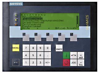
An AOP30 Advanced Operator Panel is located in the cabinet door of the converter cabinets for operation, monitoring and commissioning tasks.
The AOP30''s two-stage safety concept prevents unintentional or unauthorized changes to settings. Operation of the drive from the operator panel can be disabled using the keyboard lock so that only parameter values and process variables can be displayed on the operating panel. The default setting of the OFF key is "activated", however this can be changed by the customer to "deactivated". A password can be used to prevent the unauthorized modification of the DC converter parameters.
The user is guided by interactive menus through the drive-commissioning screens. Only 5 parameters (which can be found on the motor rating plate and the line supply data) have to be entered on the AOP30 when commissioning the system for the first time. The closed-loop control is then optimized automatically to adapt the converter to the motor.
The operator panel languages German, English and Chinese can be used without any additional memory card. French, Italian, Spanish and Russian are available on the Control Unit memory card (option). The actual unit firmware including languages can be downloaded free of charge from the Internet under the following link: http://support.automation.siemens.com/WW/view/en/38157755/133100
Communication


The units are equipped as standard with PROFIBUS - the industry standard. As a consequence, the converters can be simply and quickly integrated into the TIA environment. PROFINET is available as option. It goes without saying that communications can be established on the drive to higher-level control systems via the fieldbus. This means that using the STARTER commissioning tool, the drives can be monitored and diagnosed from a central location.
In addition to the communication interfaces, naturally there are many digital and analog inputs/outputs available; these can be used to control the converter or to output parameter values for diagnostics. The inputs and outputs are quickly and easily connected via the control terminal strip.
Control terminal strip TMC
The Terminal Module Cabinet (TMC) is located in the lower section of the cabinet, so that all of the digital and analog inputs/outputs can be quickly and simply connected. The installation space has been selected so that it is guaranteed that they are spatially separated from the power cables. Not only this, when retrofitting, the length of the existing signal cables are generally sufficient so that the signal terminals can be used. The digital input/outputs are connected via interface relays in order to guarantee operational safety and reliability. In addition to the inputs/outputs and the incremental encoder interface, optionally the tachometer connection can be routed to the control terminal strip.
Note:
A detailed terminal assignment is provided in the Section, Assignment of terminals and connectors.
Control terminal strip
Terminals for the motor fan
The basic version already includes the power supply for the motor fan. The connections are protected using a motor protection circuit breaker. The setting range of the motor protection circuit breaker must be assigned as option (W20 to W41). As option, the feeder for the motor fan can be omitted or extended by a second motor fan feeder. The feeders are switched using a contactor, which is automatically controlled from the internal sequence control of the SINAMICS DC MASTER.
Terminals for the auxiliary supply
The basic version of the drive cabinet assumes that there is an auxiliary power supply of 400 V 3 AC, 50 Hz from a grounded line supply (TN or TT supply system). The power supply is also used to supply the field and the motor fan. Optionally, other supply voltages and a line frequency of 60 Hz can be selected. It also goes without saying that an option can be selected for an internal auxiliary power supply.
Dependent on the selected options, other terminals are available, for example for the cabinet anti-condensation heating. Data regarding the terminal assignment and the connection options are provided in the description of the relevant option.
For the power connections, the maximum connection cross-sections and the number of cables that can be connected are specified in the technical data.
Closed-loop control functions
Function | Description |
|---|---|
Functions of the closed-loop control in the armature circuit | |
Speed setpoint | The source of the speed setpoint and additional setpoints can be freely selected by making the appropriate parameter settings:
|
Actual speed | One of four sources can be selected as signal for the speed actual value.
|
Ramp-function generator | When there is a step change in the setpoint applied at its input, the ramp-function generator converts the setpoint into a signal with a steady rate of rise. Ramp-up time and ramp-down time can be selected independently of one another. In addition, the ramp-function generator has initial and final rounding-off (jerk limiting) that are effective at the beginning and end of the ramp-up time. All of the times for the ramp-function generator can be set independently of one another. Three parameter sets are available for the ramp-function generator times; these can be selected via binary select inputs or a serial interface (via binectors). The ramp-up function generator parameters can be switched over in operation. In addition, a multiplication factor can be applied to the value of parameter set 1 via a connector (to change the ramp-function generator data via a connector). When entering ramp-function generator times with the value zero, the speed setpoint is directly input into the speed controller. |
Speed controller | The speed controller compares the setpoint and actual value of the speed and if there is a deviation, enters an appropriate current setpoint into the current controller (principle: Speed control with lower-level current controller). The speed controller is implemented as PI controller with additional D component that can be selected. Further, a switchable droop function can be parameterized. All of the controller parameters can be adjusted independently of one another. The value for Kp (gain) can be adapted depending on a connector signal (external or internal). In this case, the P gain of the speed controller can be adapted depending on the speed actual value, current actual value, setpoint-actual value distance or the wound roll diameter. This can be precontrolled in order to achieve a high dynamic performance in the speed control loop. For this purpose, e.g. depending on the friction and the moment of inertia of the drive, a torque setpoint signal can be added after the speed controller. The friction and moment of inertia compensation are determined using an automatic optimization run. The output quantity of the speed controller can be directly adjusted via parameter after the controller has been enabled. Depending on the parameterization, the speed controller can be bypassed and the converter controlled either with closed-loop torque or current control. In addition, it is also possible to switch between speed control/torque control in operation using the "leading/following switchover" selection function. The function can be selected as binector using a binary user-assignable terminal or a serial interface. The torque setpoint is input via a selectable connector and can therefore come from an analog user-assignable terminal or via a serial interface. A limiting controller is active when in the following drive state (torque or current controlled operation). In this case, depending on a speed limit that can be selected using parameters, the limiting controller can intervene in order to prevent the drive accelerating in an uncontrolled fashion. In this case, the drive is limited to an adjustable speed deviation. |
Torque limitation | The speed controller output represents the torque setpoint or current setpoint depending on what has been parameterized. In torque-controlled operation, the speed controller output is weighted with the machine flux φ and transferred to a current limiting stage as a current setpoint. Torque control is primarily used in field weakening operation in order to limit the maximum motor torque independent of the speed. The following functions are available:
|
Current limiting | The current limit that can be adjusted after the torque limit is used to protect the converter and the motor. The lowest specified quantity is always effective as the actual current limit. The following current limit values can be set:
|
Current controller | The current controller is implemented as PI controller with P gain and integral time that can be set independently from one another. The P and I components can also be deactivated (pure P controller or pure I controller). The current actual value is sensed using a current transformer on the three-phase side and is fed to the current controller via a load resistor and rectification after analog-digital conversion. The resolution is 10 bits for the rated current. The current limit output is used as current setpoint. The current controller output transfers the firing angle to the gating unit - the precontrol function is effective in parallel. |
Precontrol | The precontrol in the current control loop improves the dynamic performance of the closed-loop control. This allows rise times of between 6 and 9 ms in the current control loop. The precontrol is effective dependent on the current setpoint and EMF of the motor and ensures - for intermittent and continuous current or when the torque direction is reversed - that the required firing angle is quickly transferred as setpoint to the gating unit. |
Auto-reversing module | In conjunction with the current control loop, the auto-reversing module (only for units with four-quadrant drives) ensures the logical sequence of all of the operations and processes required to change the torque direction. The torque direction can also be disabled when required via parameter. |
Gating unit | The gating unit generates the firing pulses for the power section thyristors in synchronism with the line supply voltage. The synchronization is independent of the speed and the electronics supply and is sensed at the power section. The timing of the firing pulses is defined by the output values of the current controller and the precontrol. The firing angle limit can be set using parameters. In a frequency range from 45 to 65 Hz, the gating unit automatically adapts itself to the actual line frequency. |
Functions of the closed-loop control in the field circuit | |
EMF controller | The EMF controller compares the setpoint and actual value of the EMF (induced motor voltage) and enters the setpoint for the field current controller. This therefore permits field weakening control that is dependent on the EMF. |
Field current controller | The field current controller is a PI controller - where Kp and Tn can be independently set. It can also be operated as pure P and I controller. A precontrol function operates in parallel to the field current controller. This calculates and sets the firing angle for the field circuit as a function of current setpoint and line supply voltage. The precontrol supports the current controller and ensures that the field circuit has the appropriate dynamic performance. |
Gating unit | The gating unit generates the firing pulses for the power section thyristors in synchronism with the line supply voltage in the field circuit. The synchronization is detected in the power section and is therefore independent of the electronics power supply. The timing of the firing pulses is defined by the output values of the current controller and the precontrol. The firing angle limit can be set using parameters. In a frequency range from 45 to 65 Hz, the gating unit automatically adapts itself to the actual line supply voltage. |
Communication between drive components | |
DRIVE-CLiQ | Communication between SINAMICS components is realized using the standard internal SINAMICS interface DRIVE-CLiQ (this is an abbreviation for Drive Component Link with IQ). This couples the Control Unit with the connected drive components (e.g. DC converter, Terminal Modules). DRIVE-CLiQ provides standard digital interfaces for all SINAMICS drives. This permits modularization of the drive functions and thus increased flexibility for customized solutions (allows power and intelligence to be separated). The DRIVE-CLiQ hardware is based on the Industrial Ethernet standard and uses twisted-pair cables. The DRIVE-CLiQ line provides the transmit and receive signals and also the 24 V power supply. Setpoints and actual values, control commands, status feedback signals and electronic rating plate data of the drive components are transferred via DRIVE-CLiQ. Only original Siemens cables must be used for DRIVE-CLiQ cables. As a result of the special transfer and damping properties, only these cables can guarantee that the system functions perfectly. |
SINAMICS Link | SINAMICS Link allows data to be directly exchanged between several (2 to 64) Control Units. A higher-level master is not required. The following Control Units support SINAMICS Link:
In order to use SINAMICS Link, all of the Control Units must be equipped with the CBE20 Communication Board (option G20). For the Advanced CUD, a memory card is also required (options S01, S02). Communication can either be synchronous (only CU320-2) or non-synchronous or a combination of both. Each participant can send and receive up to 16 process data words. For instance, SINAMICS Link can be used for the following applications:
|
Схема подключения
Block diagrams
Representative for the converter cabinets, three single-line circuit diagrams will be subsequently shown with the principal electrical design of the basic version. Another diagram shows a cabinet version with the options that are relevant from an electrical perspective.
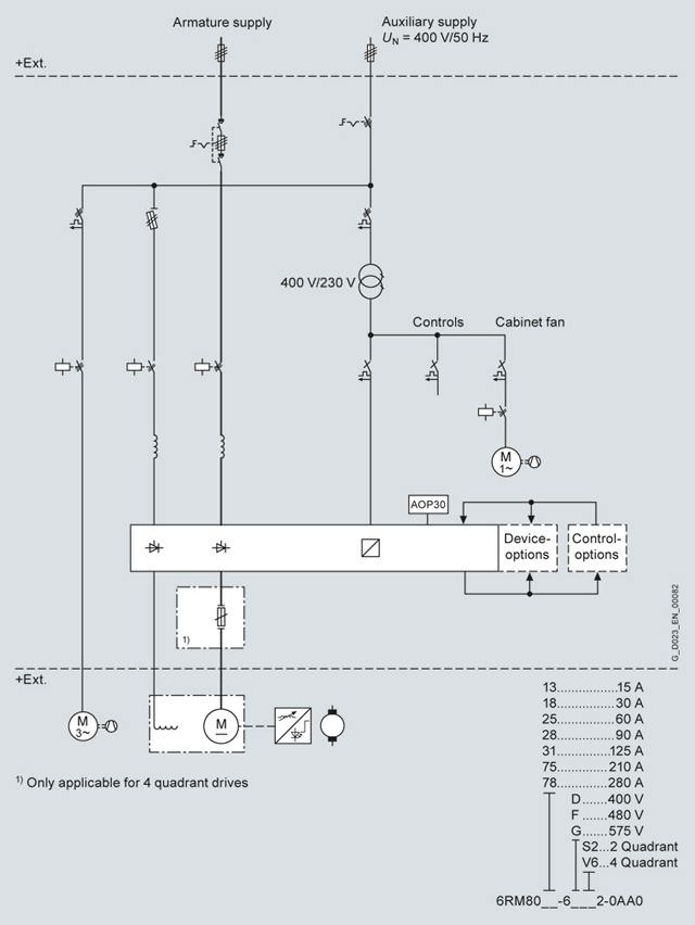
Single-line circuit diagram, rated DC current ≤ 280 A
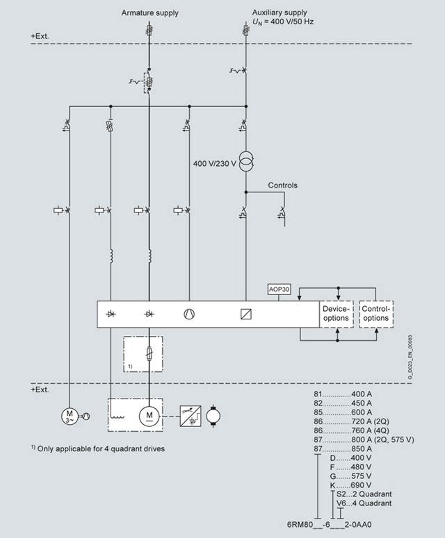
Single-line circuit diagram, rated DC current ≤ 850 A
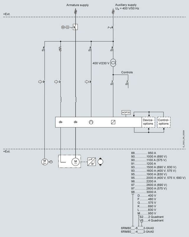
Single-line circuit diagram, rated DC current ≤ 3 000 A
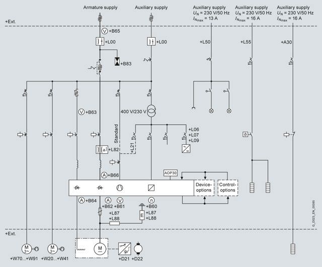
Single-line circuit diagram showing the options that are relevant from an electrical perspective
Assignment of terminals and connectors
Overview
Overview of the terminals and connector assignment of SINAMICS DC MASTER Cabinet. When using special options, additional terminals are available. A description is then provided in the particular option description.
Terminal strip | Function | Remark | Max. connectable conductor cross-section | |
|---|---|---|---|---|
Terminals | ||||
-X0 armature circuit supply | ||||
-X0 | 1 ... 3, PE | Supply, 3 AC armature circuit | Only from 15 up to 600 A, and only for option L00 (radio interference suppression filter), otherwise connected directly at the main switch or circuit breaker, -X0 is then no longer applicable. | Dependent on the rated current, refer to the technical data. |
-X1 auxiliary power supply 400 V 3 AC /50 Hz or 460 V 3 AC /60 Hz | ||||
-X1 | 1 ... 3, PE | Supply, 3 AC auxiliary power supply | In the basic version, an auxiliary power supply of 400 V 3 AC /50 Hz or 460 V 3 AC/60 Hz is required. For different voltages, option Y04 (auxiliary voltage 3 AC not the same as the standard voltage) is required. | Dependent on the option scope. |
-X2 control terminals 24 V DC/230 V AC | ||||
-X2 | 1, 2 | Group fault signal, tripped circuit breaker | Isolated contacts for 24 V DC up to max. 230 V AC. | 2.5 mm2 |
3, 4 | External Emergency Stop pushbutton | Not for option L57 or L59, circuit with 230 V AC, | 2.5 mm2 | |
5, 6 | Control interlocking of main contactor | Only for option B30 (interlocking possibility for the supply circuit breaker), circuit with 230 V AC, | 2.5 mm2 | |
21, 22 | External EMERGENCY OFF/ EMERGENCY STOP reset | Only for option L57 or L59, 24 V DC circuit. | 2.5 mm2 | |
23 ... 26 | External EMERGENCY OFF/ EMERGENCY STOP pushbutton | Only for option L57 or L59, the external EMERGENCY OFF pushbutton should be connected with channel 1 (NC contact) at terminals 23, 24, and with channel 2 (NC contact) at terminals 25, 26. The wire jumpers inserted between these terminals in the factory must be removed. | 2.5 mm2 | |
31 ... 40 | Ground fault signal, fault and alarm | Only for option L87 or L88 (ground fault monitoring in an ungrounded line supply), two isolated changeover contacts of the ground fault monitor for 24 V DC up to max. 230 V AC. These contacts can be parameterized to the required signals. A test can be initiated using an external pushbutton connected at terminals 37 and 38. A reset can be initiated using an external pushbutton (NC contact) connected at terminals 39, 40. | 2.5 mm2 | |
31 ... 40 | Fault current relay trip | Only for option L82 (fault current monitoring in an ungrounded line supply), an isolated changeover contact of the fault current relay for 24 V DC up to max. 230 V AC at terminals 31 to 33 signals the trip; an external pushbutton can be connected to terminals 37 and 38 to initiate a test trip. A reset can be initiated using an external pushbutton (NC contact) connected at terminals 39, 40. | 2.5 mm2 | |
41 ... 43 | Ruptured fuse/disconnector position 7VV3002 | Only for option B83 (overvoltage protection), isolated signaling contact, which signals a ruptured fuse or the disconnector position in the overvoltage protection, for 24 V DC up to max. 230 V AC. | 2.5 mm2 | |
51, 52, PE | 24 V DC supply voltage | Only for option L07 (24 V DC external power supply). | 4 mm2 | |
61 ... 64, PE | Motor holding brake | Only for option Y51 (motor holding brake), supply and feeder for a motor holding brake, | 2.5 mm2 | |
-X3 motor interface (field, fan) | ||||
-X3 | 1, 2, PE | Motor connection, field circuit | Connectable cross-section depends on the selected cabinet type of at least 2.5 mm2 up to 10 mm2 at 40 A – and for option L85 (field current 85 A) up to 35 mm2 can be connected. | Dependent on the cabinet type, refer to the technical data. |
3 ... 5, PE | Feeder, motor fan 1 | 4 mm2 | ||
6 ... 8, PE | Feeder, motor fan 2 | Only for options W70 to W91. | 4 mm2 | |
-X4 auxiliary power supply 1 AC 230 V (optional) | ||||
-X4 | 1, 2, PE | Supply, cabinet lighting | Only for option L50 (cabinet lighting and service outlet), | 2.5 mm2 |
3, 4, PE | Supply, cabinet heating | Only for option L55 (cabinet anti-condensation heating), | 2.5 mm2 | |
5, 6, PE | Supply, motor heating | Only for option A30 (anti-condensation heating for the motor up to max. 2 000 W, 230 V), | 2.5 mm2 | |
Terminals 1-3-5 and 2-4-6 can be connected on the customer side by inserting a wire jumper, so that these three options can also be supplied together. | ||||
6, 7, PE | Feeder, motor heating | Only for option A30 (anti-condensation heating for the motor up to max. 2 000 W, 230 V), | 2.5 mm2 | |
-X71 TMC for CUD left (standard) | ||||
-X71 | 1 ... 64 | Input/output signals of the left-hand CUD | On the terminal strip, all signals are available that exist at the CU, binary inputs/outputs, analog inputs/outputs, input for an incremental encoder, temperature measuring input, peer-to-peer interface. | 1.5 mm2 |
-X72 TMC for CUD right (optional) | ||||
-X72 | 1 ... 64 | Input/output signals of the right-hand CUD | Only for option G10 or G11 (additional CU right) | 1.5 mm2 |
SINAMICS DC MASTER Converter interfaces | ||||
X100, X101 | DRIVE-CLiQ | Only with the Advanced CUD (option G00, G11) | ||
X126 | PROFIBUS | The standard CUD and/or Advanced CUD, or for commissioning, integrated in the cabinet door (option L91). | ||
X165, X166 | Parallel interface | The standard CUD and/or Advanced CUD. | ||
X178 | RS485 interface | Assigned as standard, as this is used to connect the AOP30. | ||
(X179) | (RS232 interface) | For use as USS interface; cannot be used in parallel to interface X178. | ||
XT1 | Analog tachometer | |||
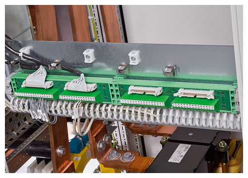
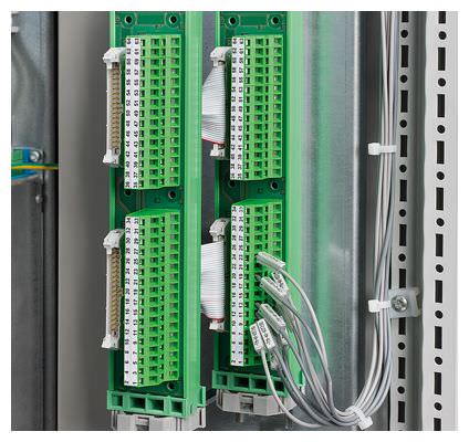
The Terminal Module Cabinet (TMC -X71, -X72)
The Terminal Module Cabinet (TMC) allows cables associated with CUD standard signals to be connected in the lower section of the SINAMICS DC MASTER Cabinet that is easy to access (e.g. digital and analog inputs/outputs, peer-to-peer interface, incremental encoder, temperature sensor). This is possible, as the appropriate interfaces (X177 of the CUD) are routed to the TMC using an adapter board (X71, X72).
TMC terminals
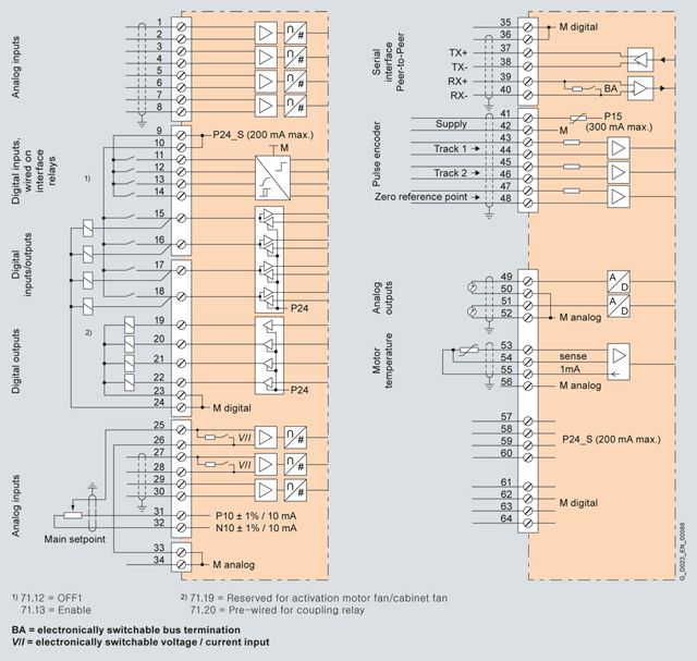
Connection diagram of the TMC with typical connections (max. 1.5 mm2)
Terminals at the Terminal Module Cabinet X71/X72
Assignment of terminals X71 (left-hand CUD) and X72 (right-hand CUD)
Terminal | Function | Technical data | ||
|---|---|---|---|---|
Analog inputs (user-assignable inputs) | ||||
1 | AI3 + | Analog input 3 | Input type (signal type): | |
3 | AI4 + | Analog input 4 | ||
5 | AI5 + | Analog input 5 | ||
7 | AI6 + | Analog input 6 | ||
Digital inputs (user-assignable inputs) | ||||
9 | 24 V DC | 24 V supply (output) | 24 V DC, short-circuit proof | |
11 | DI0 | Digital input 0 | H signal: +15 … +30 V | |
12 | DI1 | Digital input 1 | ||
13 | DI2 | Digital input 2 | ||
14 | DI3 | Digital input 3 | ||
Digital inputs/outputs (user-assignable inputs/outputs) | ||||
15 | DI/ | Digital input | Type, input/output parameterizable Output features: For overload: Alarm A60018 | |
16 | DI/ | Digital input | ||
17 | DI/ | Digital input | ||
18 | DI/ | Digital input | ||
19 | DO0 | Digital output 0 | H signal: +20 … +26 V For overload: Alarm A60018 | |
20 | DO1 | Digital output 1 | ||
21 | DO2 | Digital output 2 | ||
22 | DO3 | Digital output 3 | ||
23, 24 | M | Ground, digital | ||
Analog inputs, setpoint inputs (user-assignable inputs) | ||||
25 | AI0 + | Analog input 0 | Input type (signal type), parameterizable: | |
27 | AI1 + | Analog input 1 | ||
29 | AI2 + | Analog input 2 | Input type (signal type): | |
Reference voltage | ||||
31 | P10 | Reference voltage ± 10 V (output) | Tolerance ± 1 % at 25 °C | |
33, 34 | M | Ground, analog | ||
Serial interface, peer-to-peer RS485 | ||||
35, 36 | M | Ground, digital | ||
37 | TX+ | Send line + | 4-wire send cable, positive differential output | |
38 | TX– | Send line – | 4-wire send cable, negative differential output | |
39 | RX+ | Receive cable + | 4-wire receive cable, positive differential output | |
40 | RX– | Receive cable – | 4-wire receive cable, negative differential output | |
Incremental encoder input | ||||
41 | Incremental encoder supply | +13.7 … +15.2 V, 300 mA short-circuit proof (electronically protected) | ||
42 | Ground, incremental encoder | |||
43 | Track 1 positive connection | Load: ≤ 5.25 mA at 15 V (without switching losses) Data regarding the cables, cable length, shield support, input pulse levels, hysteresis, track offset, pulse frequency, see below | ||
44 | Track 1 negative connection | |||
45 | Track 2 positive connection | |||
46 | Track 2 negative connection | |||
47 | Zero mark, positive connection | |||
48 | Zero mark, negative connection | |||
Analog outputs (user-assignable outputs) | ||||
49 | AO0 | Analog output 0 | ± 10 V, max. 2 mA short-circuit proof, resolution ± 15 bits | |
50 | M | Ground, analog | ||
51 | AO1 | Analog output 1 | ||
52 | M | Ground, analog | ||
Connections for temperature sensor (motor interface 1) | ||||
53 | Temp 1 | Sensor acc. to p50490 | ||
54 | Temp 2 (sense cable) | |||
55 | Temp 3 | |||
Terminals for ground and the 24 V DC supply | ||||
56 | M | Ground, analog | ||
57, 58, 59, 60 | 24 V DC | 24 V supply (output) | 24 V DC, short-circuit proof, max. load 200 mA (terminals 9, 10, 57, 58, 59 and 60 together), internal supply referred to ground, digital and ground, analog | |
61, 62, 63, 64 | M | Ground, digital | ||
C98043-A7119 TMC (Terminal Module Cabinet)
Технические данные
General technical data
Coolant temperature and installation altitude
Current derating
The permissible coolant temperatures and installation altitudes for SINAMICS DC MASTER Cabinet as well as the associated maximum permissible load in continuous operation can be taken from the following table (the load is specified as a % of the rated DC current).
Note:
The rated DC current of the drive cabinets corresponds to the rated DC current of the DC converters installed in them. The degree of protection and cooling type of the drive cabinets as well as the coolant temperature and installation altitude influence the max. permissible load in continuous operation. In practice, the rated current of the DC motor lies significantly below the rated DC current of the next largest converter in order to be able to fully utilize the high overload capability of the motor. The derating factors below should be taken into account for the particular application.
Example:
Rated current of the DC motor 450 A, coolant temperature 40 °C, installation altitude of the drive cabinet 2 000 m, selected rated DC current of the converter 600 A, derating factor 81 %.
Result:
The maximum permissible load of the drive cabinet in continuous operation is 486 A, and is therefore sufficient for the motor.
Maximum permissible load of the drive cabinets in continuous operation | ||||||||||||||||||||||||||
|---|---|---|---|---|---|---|---|---|---|---|---|---|---|---|---|---|---|---|---|---|---|---|---|---|---|---|
Installation altitude above sea level | ||||||||||||||||||||||||||
Ambient or coolant temperature | Units | 1 000 m | 2 000 m | 3 000 m | 4 000 m | 5 000 m | ||||||||||||||||||||
from 1500 A ⇒ |
| ⇒ |
| ⇒ |
| ⇒ |
| ⇒ |
| |||||||||||||||||
from 950 A ⇒ |
| ⇒ |
| ⇒ |
| ⇒ |
| ⇒ |
| |||||||||||||||||
from 720 A ⇒ |
| ⇒ |
| ⇒ |
| ⇒ |
| ⇒ |
| |||||||||||||||||
from 210 A ⇒ |
| ⇒ |
| ⇒ |
| ⇒ |
| ⇒ |
| |||||||||||||||||
up to 125 A ⇒ |
| ⇒ | ⇒ | ⇒ | ⇒ | |||||||||||||||||||||
Degree of protection IP20 up to IP21 | ||||||||||||||||||||||||||
25 °C | 100% | 100% | 100% | 100% | 100% | 100% | 96% | 93% | 97% | 93%< Запрос коммерческого предложения× Сообщение отправлено× В ближайшее время сообщение будет обработано. Письмо с номером обращения отправлено на Ваш почтовый ящик. Спасибо за то, что выбрали Первый ZIP! Что-то пошло не так...× К сожалению, наша система расценила Ваше сообщение как спам. Если это произошло по ошибке, пожалуйста, обратитесь к нам по электронной почте. Приносим извинения за возможные неудобства.  Вы отправляете нам запрос  Если у нас есть прайс-лист, мы отправляем Вам ответ в течение дня. А если у нас нет прайс-листа по запрошенным товарам?     Если у нас нет прайс-листа, мы отправляем запрос производителю.  Ответ от производителя может занять до 5 дней и более. Ответ от производителя может занять до 5 дней и более.  Запрос производителю мы отправляем только для конечных потребителей.  Торгующим организациям коммерческие предложения предоставляются только по прайсовым позициям: Siemens Beckhoff Pepperl+Fuchs Phoenix Contact PILZ Turck Leuze Electronic Endress+Hauser Murr Elektronik Schmersal | ||||||||||||||||