CU230P-2 Control Units Siemens

Обзор

Example: CU230P-2 PN Control Unit
The CU230P-2 Control Units are designed for drives with integrated technological functions for pump, fan and compressor applications. The I/O interface, the fieldbus interfaces and the additional software functions optimally support these applications.
Note:
Shield plates and shield connection kits are available. These can be used in the wiring installation for the Control Units and PM230/PM240 Power Modules to ensure that it complies with EMC guidelines.
For further information, see Shield connection kits and shield plates for Control Units and Power Modules in section Supplementary system components.
PM330 Power Modules are supplied with the accessories needed to create an EMC-compliant wiring installation for Control Units and Power Modules. The Control Unit mounting surface on the Power Modules has mounting slots for shielding terminals.
Дизайн
CU230P‑2 HVAC, CU230P‑2 DP, CU230P‑2 PN and CU230P‑2 CAN Control Units
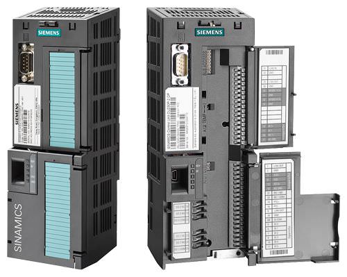
Example: CU230P‑2 Control Unit with open and closed terminal covers
Terminal No. | Signal | Features |
|---|---|---|
Digital inputs (DI) – Standard | ||
69 | DI COM | Reference potential for digital inputs |
5 ... 8. | DI0 … DI5 | Freely programmable |
Digital outputs (DO) | ||
18 | DO0, NC | Relay output 1 |
19 | DO0, NO | Relay output 1 |
20 | DO0, COM | Relay output 1 |
21 | DO1, NO | Relay output 2 |
22 | DO1, COM | Relay output 2 |
23 | DO2, NC | Relay output 3 |
24 | DO2, NO | Relay output 3 |
25 | DO2, COM | Relay output 3 |
Analog inputs (AI) | ||
3 | AI0+ | Differential input, switchable between current and voltage |
4 | AI0- | |
10 | AI1+ | Differential input, switchable between current and voltage |
11 | AI1- | |
50 | AI2+ | Non-isolated input, switchable between current and temperature sensors, type Pt1000/LG-Ni1000 |
51 | GND | Reference potential of the AI2/internal electronics ground |
52 | AI3+ | Non-isolated input for temperature sensors, type Pt1000/LG-Ni1000 |
53 | GND | Reference potential of the AI3/internal electronics ground |
Analog outputs (AO) | ||
12 | AO0+ | Non-isolated output |
13 | GND | Reference potential of the AO0/internal electronics ground |
26 | AO1+ | Non-isolated output |
27 | GND | Reference potential of the AO1/internal electronics ground |
Motor temperature sensor interface | ||
14 | T1 MOTOR | Positive input for motor temperature sensor |
15 | T2 MOTOR | Negative input for motor temperature sensor |
Power supply | ||
9 | +24 V OUT | Power supply output |
28 | GND | Reference potential of the power supply/internal electronics ground |
1 | +10 V OUT | Power supply output |
2 | GND | Reference potential of the power supply/internal electronics ground |
31 | +24 V IN | Power supply input |
32 | GND IN | Reference potential of the power supply input |
35 | +10 V OUT | Power supply output |
36 | GND | Reference potential of the power supply/internal electronics ground |
1) The following applies to systems complying with UL: A maximum of 3 A, 30 V DC or 2 A, 250 V AC may be connected via terminals 18 / 20 (DO0 NC) and 23 / 25 (DO2 NC).
Функции
Below is a list of functions sorted according to the following categories:
Control modes
- Linear and quadratic torque characteristic for fluid flow and positive displacement machines
- ECO mode for additional energy saving in U/f control mode
- Sensorless vector control for sophisticated control tasks and high-output motors
Connections
- 2 analog inputs (current/voltage can be selected) to directly connect pressure/level sensors
- 2 additional analog inputs to connect Pt1000/LG‑Ni1000 temperature sensors
- Direct control of valves and flaps using two 230 V AC relays
Interfaces
- PROFINET, EtherNet/IP, PROFIBUS, USS, BACnet MS/TP, P1 protocol, CANopen and Modbus-RTU communication
Software functions
- Automatic restart function after power failure
- Automatic restart
- Flying restart
- Skip frequencies
- 1 PID controller for the closed-loop control of the motor speed as process controller for temperature, pressure, air quality or levels
- 3 freely-programmable PID controllers
- Sleep mode
- Load check function to monitor belts and flow
- Cascade connection
- Multi-zone controller
- Essential service mode
- Real time clock with three time generators
IOP wizards for special applications with and without PID controller, such as
- Pumps: Positive displacement (constant load torque) and centrifugal pumps (quadratic load torque)
- Fans: Radial and axial fans (quadratic load torque)
- Compressors: Positive displacement (constant load torque) and fluid flow machines (quadratic load torque)
Интеграция

Connection diagram for the CU230P‑2 Control Unit series
More information about the interfaces of the Control Unit is available on the Internet at
http://support.automation.siemens.com/WW/view/en/30563628/133300

Communication interface USS, Modbus RTU, BACnet MS/TP, P1 protocol for CU230P‑2 HVAC

PROFIBUS DP communication interface

Communication interface PROFINET-EtherNet/IP

CANopen communication interface
Технические данные
Control Unit | CU230P‑2 HVAC | CU230P‑2 DP | CU230P‑2 PN | CU230P‑2 CAN |
|---|---|---|---|---|
| 6SL3243-0BB30-1HA3 | 6SL3243-0BB30-1PA3 | 6SL3243-0BB30-1FA0 | 6SL3243-0BB30-1CA3 |
Electrical specifications | ||||
Operating voltage | 24 V DC via the Power Module or by connecting to an external 20.4 ... 28.8 V DC power supply | |||
Current consumption, max. | 0.5 A | |||
Protective insulation | PELV according to EN 50178 | |||
Power loss, max. | 5 W | |||
Interfaces | ||||
Digital inputs – Standard | 6 isolated inputs, optically isolated; NPN/PNP logic can be selected using the wiring | |||
| 11 V | |||
| 5 V | |||
| 5.5 mA | |||
Digital outputs | 3 relays | |||
| 250 V AC, 2 A (inductive load) | |||
| 30 V DC, 0.5 A (ohmic load) | |||
Analog inputs | Analog inputs are protected against inputs in a voltage range of ± 30 V and have a common-mode voltage in the ± 15 V range | |||
| Switchable with DIP switch between voltage and current: These differential inputs can be configured as additional digital inputs. | |||
| Switchable with DIP switch between 0/4 ... 20 mA current and temperature sensor type Pt1000/LG‑Ni1000, | |||
| Temperature sensor type Pt1000/LG‑Ni1000, | |||
Analog outputs | The analog outputs have short circuit protection | |||
| Switchable between voltage and current using parameter setting: Voltage mode: 10 V, min. burden 10 kΩ | |||
PTC/KTY interface | 1 motor temperature sensor input, | |||
Bus interface | ||||
Fieldbus protocols |
|
|
|
|
Profile | – |
|
| – |
Hardware | Plug-in terminal, insulated, | 9-pin SUB-D socket, insulated, | 2 × RJ45, PROFIdrive profile V4.1, device name can be stored on the device Max. 100 Mbit/s (full duplex) | 9-pin SUB-D connector, insulated, |
Control Unit | CU230P‑2 HVAC | CU230P‑2 DP | CU230P‑2 PN | CU230P‑2 CAN |
|---|---|---|---|---|
| 6SL3243-0BB30-1HA3 | 6SL3243-0BB30-1PA3 | 6SL3243-0BB30-1FA0 | 6SL3243-0BB30-1CA3 |
Tool interfaces | ||||
Memory card | SINAMICS SD card | |||
Operator panels |
| |||
| Can be directly plugged on | |||
| Can be directly plugged on | |||
| Required when no operator panel is plugged in order to achieve degree of protection IP55 on PM230 Power Modules degree of protection IP55/UL Type 12 | |||
PC interface | USB (connection via PC inverter connection kit 2) | |||
Open-loop/closed-loop control techniques | ||||
U/f linear/quadratic/parameterizable | ✓ | |||
U/f with flux current control (FCC) | ✓ | |||
U/f ECO; linear/quadratic | ✓ | |||
Vector control, sensorless | ✓ | |||
Torque control, sensorless | ✓ | |||
Software functions | ||||
Setpoint input | ✓ | |||
Fixed frequencies | 16, parameterizable | |||
JOG | ✓ | |||
Digital motorized potentiometer (MOP) | ✓ | |||
Ramp smoothing | ✓ | |||
Extended ramp-function generator (with ramp smoothing OFF3) | ✓ | |||
Slip compensation | ✓ | |||
Signal interconnection with BICO technology | ✓ | |||
Free function blocks (FFB) for logical and arithmetic operations | ✓ | |||
Switchable drive data sets (DDS) | ✓ (4) | |||
Switchable command data sets (CDS) | ✓ (4) | |||
Flying restart | ✓ | |||
Automatic restart after line supply failure or operating fault (AR) | ✓ | |||
Technology controller (internal PID) | ✓ | |||
Sleep mode with internal/external PID controller | ✓ | |||
Belt monitoring with and without sensor (load torque monitoring) | ✓ | |||
Dry-running/overload protection monitoring (load torque monitoring) | ✓ | |||
Thermal motor protection | ✓ (I2t, sensor: PTC/KTY/bimetal) | |||
Thermal inverter protection | ✓ | |||
Motor identification | ✓ | |||
Auto-ramping (Vdcmax controller) | ✓ | |||
Kinetic buffering (Vdcmin controller) | ✓ | |||
Possible braking functions |
| |||
Control Unit | CU230P‑2 HVAC | CU230P‑2 DP | CU230P‑2 PN | CU230P‑2 CAN |
|---|---|---|---|---|
| 6SL3243-0BB30-1HA3 | 6SL3243-0BB30-1PA3 | 6SL3243-0BB30-1FA0 | 6SL3243-0BB30-1CA3 |
Mechanical specifications and ambient conditions | ||||
Degree of protection | IP20 | |||
Signal cable cross-section | 0.15 ... 1.5 mm2 (AWG28 ... AWG16) | |||
Operating temperature | For CU230P‑2 HVAC/DP/CAN: -10 ... 60 °C (14 ... 140 °F) For CU230P‑2 PN: -10 ... 55 °C (14 ... 131 °F) With IOP/BOP‑2: 0 ... 50 °C (32 ... 122 °F) Derating of 3 K/1000 m applies to Control Units as of an installation altitude of 1000 m (3281 ft) above sea level. | |||
Storage temperature | -40 ... +70 °C (-40 ... +158 °F) | |||
Relative humidity | <95 % RH, condensation not permissible | |||
Dimensions |
| |||
| 73 m (2.87 in) | |||
| 199 m (7.83 in) | |||
| 65.5 mm (2.58) | |||
Weight, approx. | 0.61 kg (1.35 lb) | |||


 Ответ от производителя может занять до 5 дней и более.

