PM230 Power Modules Siemens
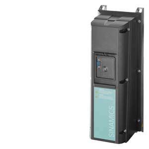
Обзор
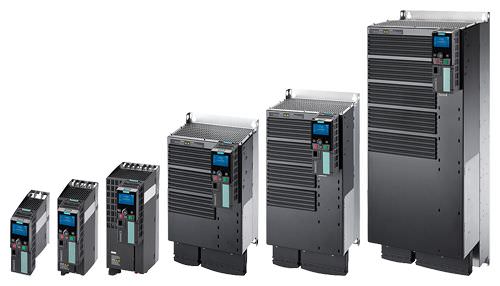
PM230 Power Modules, degree of protection IP20, frame sizes FSA to FSF (with Control Unit and operator panel)
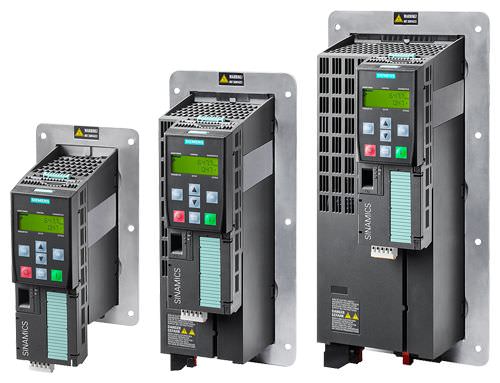
PM230 Power Modules, degree of protection IP20, Push Through variant, frame sizes FSA to FSC (with Control Unit and operator panel)
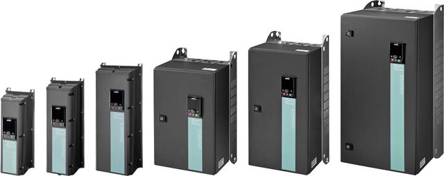
PM230 Power Modules, degree of protection IP54, frame sizes FSA to FSF (with operator panel)
PM230 Power Modules are designed for applications involving pumps, fans and compressors with a quadratic characteristic. They do not have an integrated braking chopper (single-quadrant applications).
The PM230 Power Module only generates low line harmonics and apparent power losses. In addition to the energy-related advantages, environmental stressing is also reduced.
- Line harmonics are reduced significantly.
- The limit values of EN 61000‑3‑2, EN 61000‑3‑12 or IEC 61000‑3‑4 are maintained for RSCE > 250.
RSCE is the short-circuit power ratio Ssc line/Sinverter acc. to EN 61000‑3‑2, EN 61000‑3‑12 or EN 61000‑3‑4 and is identical to RSC acc. to IEC 60146‑1‑1 in the case of three-phase devices. - Additional components such as line reactors are not required and it is not permissible to use them. As a consequence, low envelope dimensions are obtained for space-saving designs.
- The limit values of EN 61000‑3‑2, EN 61000‑3‑12 or IEC 61000‑3‑4 are maintained for RSCE > 250.
- The active power component is very high, i.e. the devices consume less current from the supply for the same drive power. As a consequence, smaller supply cables can be used.
Frame sizes FSA to FSF of the PM230 Power Module in degree of protection IP55/UL Type 12 are available with integrated line filter class A for Category C2 installations in accordance with EN 61800‑3. The PM230 Power Modules with integrated filter class B that are available as an alternative also comply with the conducted interference requirements for Category C1 in accordance with EN 61800‑3.
Frame sizes FSA to FSF of the PM230 Power Module in degree of protection IP20 are available with integrated line filter class A for Category C2 installations in accordance with EN 61800‑3, or without an integrated line filter.
Frame sizes FSA to FSC of the PM230 Power Module in degree of protection IP20 Push Through variant are available with integrated line filter class A for Category C2 installations in accordance with EN 61800‑3, or without an integrated line filter.
In order to maintain EMC categories C2 (line filter A) or C1 table 14 (line filter B, conducted), the permissible shielded cable length between the inverter and motor is limited to max. 25 m (82 ft).
The permissible cable lengths between inverter and motor are limited. Longer cables can be used if output reactors are connected for PM230 (see load-side power components).
The line system configurations that are supported are symmetrical systems with grounded neutral point.
PM230 Power Modules do not support Control Units with Safety Integrated. Safety functions can be implemented by means of external switching devices.
Note:
Shield plates and shield connection kits are available. These can be used in the wiring installation for the Control Units and Power Modules to ensure that it complies with EMC guidelines.
For further information, see Shield connection kits and Shield plates for Control Units and Power Modules in section Supplementary system components.
Характеристика
Derating data for PM230 Power Modules
Pulse frequency
Rated power 1) | Rated output current in A for a pulse frequency of | |||||||
|---|---|---|---|---|---|---|---|---|
400 V | 460 V | |||||||
kW | hp | 4 kHz | 6 kHz | 8 kHz | 10 kHz | 12 kHz | 14 kHz | 16 kHz |
0.37 | 0.5 | 1.3 | 1.11 | 0.91 | 0.78 | 0.65 | 0.59 | 0.52 |
0.55 | 0.75 | 1.7 | 1.45 | 1.19 | 1.02 | 0.85 | 0.77 | 0.68 |
0.75 | 1.0 | 2.2 | 1.87 | 1.54 | 1.32 | 1.10 | 0.99 | 0.88 |
1.1 | 1.5 | 3.1 | 2.64 | 2.17 | 1.86 | 1.55 | 1.40 | 1.24 |
1.5 | 2.0 | 4.1 | 3.49 | 2.87 | 2.46 | 2.05 | 1.85 | 1.64 |
2.2 | 3.0 | 5.9 | 5.02 | 4.13 | 3.54 | 2.95 | 2.66 | 2.36 |
3.0 | 4.0 | 7.7 | 6.55 | 5.39 | 4.62 | 3.85 | 3.47 | 3.08 |
4.0 | 5.0 | 10.2 | 8.67 | 7.14 | 6.12 | 5.1 | 4.59 | 4.08 |
5.5 | 7.5 | 13.2 | 11.22 | 9.24 | 7.92 | 6.6 | 5.94 | 5.28 |
7.5 | 10 | 18.0 | 15.3 | 12.6 | 10.8 | 9.0 | 8.1 | 7.2 |
11.0 | 15 | 26.0 | 22.1 | 18.2 | 15.6 | 13.0 | 11.7 | 10.4 |
15.0 | 20 | 32.0 | 27.2 | 22.4 | 19.2 | 16.0 | 14.4 | 12.8 |
18.5 | 25 | 38.0 | 32.3 | 26.6 | 22.8 | 19.0 | 17.1 | 15.2 |
22 | 30 | 45.0 | 38.25 | 31.5 | 27.0 | 22.5 | 20.25 | 18.0 |
30 | 40 | 60.0 | 51.0 | 42.0 | 36.0 | 30.0 | 27.0 | 24.0 |
37 | 50 | 75.0 | 63.75 | 52.5 | 45.0 | 37.5 | 33.75 | 30.0 |
45 | 60 | 90.0 | 76.5 | 63.0 | 54.0 | 45.0 | 40.5 | 36.0 |
55 | 75 | 110 | 93.5 | 77.0 | 66.0 2) | 55.0 2) | 49.5 2) | 44.0 2) |
75 | 100 | 145 | 123.3 | 101.5 | – | – | – | – |
90 | 125 | 178 | 151.3 | 124.6 | – | – | – | – |
1) Rated power based on the rated output current Irated. The rated output current Irated is based on the duty cycle for low overload (LO).
2) Values apply only to IP20 variants.
Ambient temperature
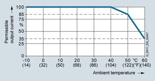
Permissible output current as a function of ambient temperature for low overload (LO) for PM230 Power Modules, frame sizes FSA to FSC

Permissible output current as a function of ambient temperature for low overload (LO) for PM230 Power Modules, frame sizes FSD to FSF

Permissible output current as a function of ambient temperature for high overload (HO) PM230 Power Modules, frame sizes FSA to FSC

Permissible output current as a function of ambient temperature for high overload (HO) PM230 Power Modules, frame sizes FSD to FSF
Note:
The operating temperature ranges of the Control Units should be taken into account. The temperature ranges are specified in the section Technical specifications under Control Units.
Installation altitude
Permissible line supplies depending on the installation altitude
- Installation altitude up to 2 000 m (6562 ft) above sea level
- Connection to every supply system permitted for the inverter
- Installation altitudes between 2 000 m (6562 ft) and 4 000 (13124 ft) m above sea level
- Connection to a TN system with grounded neutral point
- TN systems with grounded line conductor are not permitted
- The TN line system with grounded neutral point can also be supplied using an isolation transformer
- The phase-to-phase voltage does not have to be reduced
Note:
The connected motors, power elements and components must be considered separately.

Permissible output current as a function of the installation altitude for PM230 Power Modules, frame sizes FSA to FSF
System operating voltage
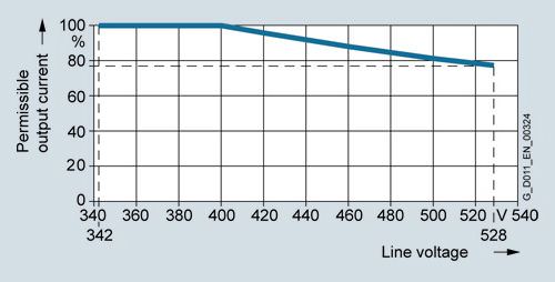
Permissible output current as a function of the line voltage for PM230 Power Modules, frame sizes FSA to FSF
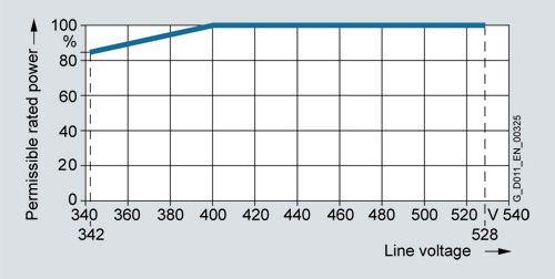
Permissible rated power as a function of the line voltage for PM230 Power Modules, frame sizes FSA to FSF
Интеграция
PM230 Power Modules have the following connections and interfaces:
- PM‑IF interface to connect the PM230 Power Module to the Control Unit. The PM230 Power Module also supplies power to the Control Unit using an integrated power supply.
- Motor connection using screw terminals or screw studs
- 2 PE/protective conductor connections
PM230 Power Modules communicate with the Control Unit via the PM-IF interface.
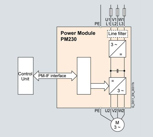
Connection diagram for PM230 Power Module with or without integrated line filter class A or B
Power components that are optionally available depending on the Power Module used
The following line-side and load-side power components are optionally available in the appropriate frame sizes for the Power Modules:
| Frame size | |||||
|---|---|---|---|---|---|---|
| FSA | FSB | FSC | FSD | FSE | FSF |
PM230 Power Module (IP54/IP55) | ||||||
Available frame sizes | ✓ | ✓ | ✓ | ✓ | ✓ | ✓ |
Line-side power components | ||||||
Line filter class A | I | I | I | I | I | I |
Line filter class B | I | I | I | I | I | I |
Line reactor 1) | – 1) | – 1) | – 1) | – 1) | – 1) | – 1) |
Load-side power components | ||||||
Output reactor | S | S | S | S | S | S |
Sine-wave filter | – | – | – | S | S | S |
PM230 Power Module (IP20) | ||||||
Available frame sizes | ✓ | ✓ | ✓ | ✓ | ✓ | ✓ |
Line-side power components | ||||||
Line filter class A | F | F | F | F | F | F |
Line filter class B | U 2) | U 2) | U 2) | S | S | S |
Line reactor 1) | – 1) | – 1) | – 1) | – 1) | – 1) | – 1) |
Load-side power components | ||||||
Output reactor | S | S | S | S | S | S |
Sine-wave filter | – | – | – | S | S | S |
U = Base component
S = Lateral mounting
I = Integrated
F = Power Modules available with and without integrated filter class A
– = Not possible
1) A line reactor is not required and must not be used in conjunction with a PM230 Power Module.
2) Lateral mounting is the only possible option for Push Through variants.
Maximum permissible cable lengths from the motor to the inverter when using output reactors or filters depending on the voltage range and the Power Module being used
The following load-side power components in the appropriate frame sizes are optionally available for the Power Modules and result in the following maximum cable lengths:
| Maximum permissible motor cable lengths (shielded/unshielded) in m | |||||
|---|---|---|---|---|---|---|
Frame size | FSA | FSB | FSC | FSD | FSE | FSF |
PM230 Power Module degree of protection IP20 | ||||||
Available frame sizes | ✓ | ✓ | ✓ | ✓ | ✓ | ✓ |
Without output reactor/sine-wave filter | 25/100 (82/328) | 25/100 (82/328) | 25/100 (82/328) | 25/100 (82/328) | 25/100 (82/328) | 25/100 (82/328) |
With optional output reactor |
|
|
|
|
|
|
| 150/225 (492/738) | 150/225 (492/738) | 150/225 (492/738) | – | – | – |
| 100/150 (328/492) | 100/150 (328/492) | 100/150 (328/492) | – | – | – |
| – | – | – | 200/300 (656/984) | 200/300 (656/984) | 200/300 (656/984) |
| – | – | – | 200/300 (656/984) | 200/300 (656/984) | 200/300 (656/984) |
With optional sine-wave filter |
|
|
|
|
|
|
| – | – | – | 200/300 (656/984) | 200/300 (656/984) | 200/300 (656/984) |
| – | – | – | 200/300 (656/984) | 200/300 (656/984) | 200/300 (656/984) |
With integrated line filter class A (EMC category C3) |
|
|
|
|
|
|
| 50/– (164/–) | 50/– (164/–) | 50/– (164/–) | 50/– (164/–) | 50/– (164/–) | 50/– (164/–) |
| 50/– (164/–) | 50/– (164/–) | 50/– (164/–) | 50/– (164/–) | 50/– (164/–) | 50/– (164/–) |
With optional external line filter class B (EMC category C1 1), with unfiltered Power Module, maintains the limit values acc. to EN 61800‑3) |
|
|
|
|
|
|
| 50/– (164/–) | 50/– (164/–) | 50/– (164/–) | 50/– (164/–) | 50/– (164/–) | 50/– (164/–) |
| 50/– (164/–) | 50/– (164/–) | 50/– (164/–) | 50/– (164/–) | 50/– (164/–) | 50/– (164/–) |
With optional external line filter class B and output reactor (EMC category C2 1), with unfiltered Power Module, maintains the limit values acc. to EN 61800‑3) |
|
|
|
|
|
|
| 150/– (492/–) | 150/– (492/–) | 150/– (492/–) | – | – | – |
| 100/– (328/–) | 100/– (328/–) | 100/– (328/–) | – | – | – |
1) Further information is available on the Internet at www.siemens.com/sinamics-g120/documentation
Чертеж
PM230 Power Modules, degree of protection IP55/UL Type 12

Principle dimension drawing and drill pattern for PM230 Power Modules, degree of protection IP55/UL Type 12 with integrated line filter class A/B
Frame size | Dimensions in mm (inches) | Drilling dimensions in mm (inches) | Cooling clearance in mm (inches) | Mounting | ||||||
|---|---|---|---|---|---|---|---|---|---|---|
| a | b | c | d | e | f | top | bottom | side | With bolts, nuts and washers |
PM230 Power Modules, degree of protection IP55/UL Type 12 with integrated line filter class A/B | ||||||||||
FSA | 154 | 460 | 249 | 132 | 445 | 11 | 100 | 0 | 0 | 4 × M4 |
FSB | 180 | 540 | 249 | 158 | 524 | 11 | 100 | 0 | 0 | 4 × M4 |
FSC | 230 | 620 | 249 | 208 | 604 | 11 | 125 | 0 | 0 | 4 × M5 |
FSD | 320 | 640 | 329 | 285 | 600 | 17.5 | 300 | 0 | 50 | 4 × M8 |
FSE | 320 | 751 | 329 | 285 | 710 | 17.5 | 300 | 0 | 50 | 4 × M8 |
FSF | 410 | 915 | 416 | 370 | 870 | 20 | 350 | 0 | 50 | 4 × M8 |
1) Increased depth:
• When the IOP is plugged on, the depth increases by 17 mm (0.67 in)
• When the BOP‑2/blanking cover is plugged on, the depth increases by 7 mm (0.28 in)
2) Up to 40 °C (104 °F) without any lateral clearance.
PM230 Power Modules, degree of protection IP20, Standard variant

Principle dimension drawing and drill pattern for PM230 Power Modules, degree of protection IP20, Standard variant, with/without integrated line filter class A
Frame size | Dimensions in mm (inches) | Drilling dimensions in mm (inches) | Cooling clearance in mm (inches) | Mounting | ||||||
|---|---|---|---|---|---|---|---|---|---|---|
| a | b | c | d | e | f | top | bottom | side 2) | With bolts |
PM230 Power Modules, degree of protection IP20, Standard variant, with/without integrated line filter class A | ||||||||||
FSA | 73 | 196 | 165 | 62.3 | 186 | 6 | 80 | 100 | 0 | 3 × M4 |
FSB | 100 | 292 | 165 | 80 | 281 | 6 | 80 | 100 | 0 | 4 × M4 |
FSC | 140 | 355 | 165 | 120 | 343 | 6 | 80 | 100 | 0 | 4 × M5 |
FSD | 275 | 419/512 | 204 | 235 | 325/419 | 11 | 300 | 300 | 0 | 4 × M6 |
FSE | 275 | 499/635 | 204 | 235 | 405/541 | 11 | 300 | 300 | 0 | 4 × M6 |
FSF | 350 | 634/934 | 316 | 300 | 598/899 | 11 | 350 | 350 | 0 | 4 × M8 |
1) Increased depth:
• When the CU230P-2 Control Unit is plugged on, the depth increases by 58 mm (2.28 in) for FSA to FSC and by 49 mm (1.93 in) for FSD to FSF
• When the IOP is plugged on, the depth increases by a further 22 mm (0.87 in)
• When the BOP‑2 is plugged on, the depth increases by a further 12 mm (0.47 in)
2)The Power Modules can be mounted side by side. A side clearance of 1 mm (0.04 in) is recommended for tolerance-related reasons.


 Ответ от производителя может занять до 5 дней и более.

