Technical Information Siemens
Обзор
SIMOTICS FD motor series
A wide range of requirements are placed on state-of-the-art, high-output, low-voltage motors. They should be energy efficient, able to be flexibly used, quiet in operation and optimally adapted to the converter, for example. All of these requirements are fulfilled by the SIMOTICS FD series of motors, which have been specifically developed for this purpose. As a result of their flexibility and the wide range of versions available, SIMOTICS FD motors are suitable for all industries.
Versions of the SIMOTICS FD motor series
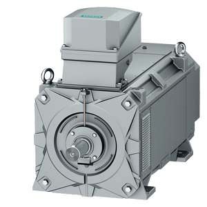
1LM1 motors
The motors are squirrel-cage induction motors with compact dimensions in a surface-cooled, enclosed version with self-ventilation. They have been specifically designed for converter-fed operation.
Note:
For frame size 355 and rated speeds of 3000 rpm and above, a shaft-mounted unidirectional fan is used.
1LM1 for converter-fed operation
- Converter-fed operation, optimally harmonized to the SINAMICS drive system
- Maximum A-weighted sound pressure level at rated speed is 79 dB(A) under no-load operation
- IP54/IP55 degree of protection
- Cooling method IC411, self-ventilated
- Housing: cast-iron
1LQ1 motors
The motors are squirrel-cage induction motors with compact dimensions in a surface-cooled, enclosed version with forced-air cooling. These motors can be operated with constant torque, also significantly below the rated speed, thanks to the forced-air cooling. They have been specifically designed for converter-fed operation.
1LQ1 for converter-fed operation
- Converter-fed operation, optimally harmonized to the SINAMICS drive system
- Maximum A-weighted sound pressure level at rated speed is 79 dB(A) or 85 dB(A) under no-load operation
- IP54/IP55 degree of protection
- Cooling method IC416, forced-air cooling
- Housing: cast-iron
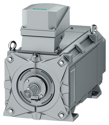
1LL1 motors
The motors are squirrel-cage induction motors with compact dimensions in a surface-cooled, open version with self-ventilation. The internal cooling circuit is supplied with cooling air from the outside. This is the reason why the output was able to be increased by approximately 30 % as compared to the 1LM1 motors. They have been specifically designed for converter-fed operation.
Note:
For frame size 355 and rated speeds of 3000 rpm and above, a shaft-mounted unidirectional fan is used.
The 1LL1 motors are designed for indoor use. They must not be subjected to humid, salty or corrosive (e.g. hydrogen sulfide) atmospheres.
1LL1 for converter-fed operation
- Converter-fed operation, optimally harmonized to the SINAMICS drive system
- Maximum A-weighted sound pressure level at rated speed is 79 dB(A) under no-load operation
- IP23 degree of protection
- Cooling method IC01, self-ventilated
- Housing: cast-iron
1LP1 motors
The motors are squirrel-cage induction motors with compact dimensions in a surface-cooled, open version with forced-air cooling. The internal cooling circuit is supplied with cooling air from the outside. This is the reason why the output was able to be increased by approximately 35 % as compared to the 1LM1 motors. These motors can be operated with constant torque, also significantly below the rated speed, thanks to the forced-air cooling. They have been specifically designed for converter-fed operation.
The 1LP1 motors are designed for indoor use. They must not be subjected to humid, salty or corrosive (e.g. hydrogen sulfide) atmospheres.
1LP1 for converter-fed operation
- Converter-fed operation, optimally harmonized to the SINAMICS drive system
- Maximum A-weighted sound pressure level at rated speed is 79 dB(A) or 85 dB(A) under no-load operation
- IP23 degree of protection
- Cooling method IC06, forced-air cooling
- Housing: cast-iron
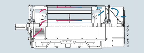
1LH1 motors
The motors are squirrel-cage induction motors with compact dimensions in an enclosed, water-cooled version. This is the reason why the output was able to be increased by approximately 30 % as compared to the 1LM1 motors. These motors can be operated with constant torque, significantly below the rated speed, as a result of the water cooling. They have been specifically designed for converter-fed operation, and are also available in a version for mains-fed operation.
1LH1 for converter-fed operation
- Converter-fed operation, optimally harmonized to the SINAMICS drive system
- Maximum A-weighted sound pressure level at rated speed is 79 dB(A) under no-load operation
- IP54/IP55 degree of protection
- Cooling method IC71W, water-cooled
- Water-jacket cooling with either a copper or stainless steel jacket
- Housing: cast-iron
1LH1 for mains-fed operation
- Maximum A-weighted sound pressure level depending on the number of poles 68 to 72 dB(A) under no-load operation
- IP54/IP55 degree of protection
- Cooling method IC71W, water-cooled
- Water-jacket cooling with either a copper or stainless steel jacket
- Housing: cast-iron
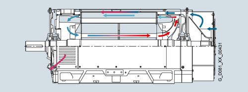
1LN1 motors
The motors are squirrel-cage induction motors with compact dimensions in a surface-cooled, enclosed version with air-towater heat exchanger. A separately driven fan is used to circulate air through the internal cooling circuit. This is the reason why the output was able to be increased by approximately 30 % as compared to the 1LM1 motors. These motors can be operated with constant torque, significantly below the rated speed, as a result of the forced-air cooling with air-to-water heat exchanger. They have been specifically designed for converter-fed operation.
1LN1 for converter-fed operation
- Converter-fed operation, optimally harmonized to the SINAMICS drive system
- Maximum A-weighted sound pressure level at rated speed is 79 dB(A) under no-load operation
- IP54/IP55 degree of protection
- Cooling method IC86W, air-to-water heat exchanger
- Housing: cast-iron
Дизайн
The basic design of the SIMOTICS FD motor series
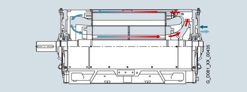
1LM1 self-ventilated motors – enclosed version
1LL1 self-ventilated motors – open version
1LH1 water-cooled motors with water-jacket cooling
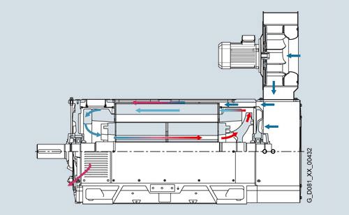
1LQ1 forced-air cooled motors – enclosed version
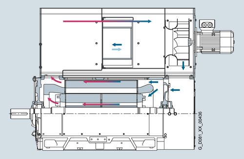
1LP1 forced-air cooled motors – open version
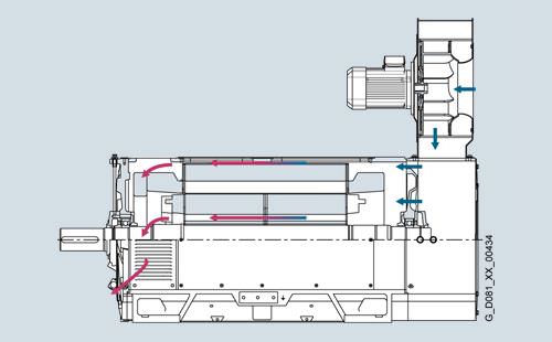
1LN1 water-cooled motors with air-to-water heat exchanger
Технические данные
Applicable standards and specifications
The SIMOTICS FD motors comply with the IEC60034 series of international product standards for rotating electrical machines and, in particular, those parts that are listed in the table below.
Title | IEC/EN | DIN EN |
|---|---|---|
General specifications for rotating electrical machines | IEC 60034‑1, | DIN EN 60034‑1 |
Specification of the losses and efficiency of rotating electrical machines | IEC 60034‑2‑1 | DIN EN 60034‑2‑1 |
Starting performance of rotating electrical machines | IEC 60034‑12 | DIN EN 60034‑12 |
Terminal designations and direction of rotation for electrical machines | IEC 60034‑8 | DIN EN 60034‑8 |
Designation for types of construction, mounting and terminal box position (IM code) | IEC 60034‑7 | DIN EN 60034‑7 |
Terminal box cable entries | – | DIN 42925 |
Built-in thermal protection | IEC 60034‑11 | DIN EN 60034‑11 |
Noise limits of rotating electrical machines | IEC 60034‑9 | DIN EN 60034‑9 |
IEC standard voltages | IEC 60038 | DIN IEC 60038 |
Methods of cooling of rotating electrical machines (IC code) | IEC 60034‑6 | DIN EN 60034‑6 |
Vibration severity of rotating electrical machines | IEC 60034‑14 | DIN EN 60034‑14 |
Vibration limits | – | DIN ISO 10816 |
Degrees of protection for rotating electrical machines (IP code) | IEC 60034‑5 | DIN EN 60034‑5 |
International efficiency classes for rotating electrical machines (IE code) | IEC 60034‑30 | DIN EN 60034‑30 |
In addition, the following applies to Ex motors: | ||
General provisions | IEC/EN 60079‑0 | DIN EN 60079‑0 |
Type of protection "n" (non-sparking) | IEC/EN 60079‑15 | DIN EN 60079‑15 |
Areas containing flammable dust | IEC/EN 60079‑31 | DIN EN 60079‑31 |
Rating plate
In accordance with EN 60034-1, the approximate total weight is specified on the rating plate. An extra rating plate can be supplied loose for all motors, order code K31.
An extra rating plate for identification codes is also possible, order code Y82.
As standard, the rating plate is in English.
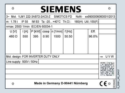
Example of a rating plate for 1LM1 for converter-fed operation
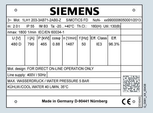
Example of a rating plate for 1LH1 for mains-fed operation
All motors that comply with the international standard IEC 60034 30:2008 (Rotating electrical machines – Part 30: Efficiency classes of single-speed, three-phase, cage-induction motors (IE code)) have the efficiency class and the efficiency stamped on the rating plate. These efficiencies are based, according to the above standard, on the losses determined in accordance with standard IEC 60034-2-1:2007.
Motors specially designed for converter-fed operation
These motors have been specifically designed for converter-fed operation. The catalog data – especially the sound pressure level at the rated speed in no-load operation – are valid for operation with a SINAMICS converter (from firmware Version 4.6 and higher).
When operated with an alternative converter, the catalog data apply (thermal torque limits, maximum overload torques), with the exception of the sound pressure level, under the following boundary conditions:
- The converter is operated with a rated pulse frequency of atleast 2.5 kHz.
- The converter can provide the rated voltage as listed in the catalog. This means that it is known whether the infeed (rectifier) is regulated or unregulated.
If the infeed is unknown, an unregulated infeed should be assumed, and the motor output should be reduced (please inquire).
For SINAMICS converters (from firmware Version 4.6 and higher), the SIMOTICS FD motor series can be selected as motor category in the SINAMICS converter using the STARTER commissioning tool software or on the converter operator panel (AOP – Advanced Operation Panel).
Rated voltage
The tolerance for the rated voltage is in accordance with DIN EN 60034-1. No rated voltage range is specified.
The rated motor voltages are selected so that when operated with a SINAMICS converter, the available voltage is optimally
utilized.
In addition to the line voltage, the type of converter infeed (regulated or unregulated rectifier) defines the motor voltage that is available. A converter with controlled rectifier always provides the motor with a higher voltage than a converter with unregulated rectifier.
Note:
When operating at the limits of voltage ranges A and B, the temperatures and overtemperatures exceed the limits specified in the standard. Under certain circumstances, this can affect the service life (continuous duty with undervoltage, on request).
Insulation
The well-proven DURIGNIT IR 2000 insulation system is used adapted to the motor and converter. The insulation system corresponds to stress category or impulse insulation class (IIC) C (significant stress according to the preliminary standard DIN IES/TS 60034-18-41: 2007-04) for operation on a two-level converter, and is subdivided into two categories. The level of converter DC-link voltage and the rise times of the voltage are important factors in the voltage stress of the winding:
- For a converter DC-link voltage of UDC,max < 700 V (line voltage 500 V with unregulated infeed), the insulation system IIC C 500 is used.
- For a converter DC-link voltage of over UDC = 700 V up to UDC = 700 V up to UDC,max = 1035 V (line voltage 500 V with regulated infeed), the insulation system IIC C 690 is used.
- The following applies for the voltage rise time: Ta > 0.5 μs.
For converter-fed operation with the outputs specified in the catalog, the motors can be utilized corresponding to thermal class 155 (F) (service factor 1.0).
In the case of a fault when connected to an IT supply system (ground fault), the insulation is excessively stressed. In this case, the process should be terminated as quickly as possible (t < 2 h), and the fault resolved. We do not recommend operation on TN supply systems with transition-point grounding.
Noise
The motors have been designed, so that at every rated speed a maximum sound pressure level of
- LPA = 79 dB(A) for self-ventilated, forced-air cooled motors and motors with air-to-water heat exchanger (1LM1, 1LL1, 1LP1, 1LQ1, 1LN1) as well as with forced-air cooling in low-noise version (1LQ1, 1LP1, position 5 of Article No. = 2)
- LPA = 85 dB(A) for motors with forced-air cooling in increased output version (1LQ1, 1LP1, position 5 of Article No. = 3)
- LPA = 78 dB(A) for water-cooled motors (1LH1)
when operated with SINAMICS converters (from firmware Version 4.6 and higher) in no-load operation is maintained.
Forced-air cooling
The separately driven fans of motors of the 1LQ1 and 1LP1 series as well as the separately driven fans in the air-to-water heat exchangers for the 1LN1 series are especially quiet. The line voltage and frequency for the forced-air cooled motors are specified, as for the motor itself, in position 12 of the Article No.
Technical specifications of the separately driven fan motor (1LQ1, 1LP1) 1)
Frame size | 5th position of the Article No. | Mounting position | PN, 50 Hz | IN, 400 V, 50 Hz | PN, 60 Hz | IN, 460 V, 60 Hz |
kW | A | kW | A | |||
315 | 2 | radial | 1.5 | 3.2 | 2.24 | 3.9 |
2 | axial | 1.75 | 3.2 | a.A. | a.A. | |
3 | radial | 5.5 | 10.5 | 5.5 | 9.1 | |
355 | 2 | radial | 1.5 | 3.2 | 2.24 | 3.9 |
2 | axial | 1.5 | 3.2 | 2.24 | 3.9 | |
3 | radial | 5.5 | 10.5 | 5.5 | 9.1 |
1) The motor data on the rating plate can deviate from this.
Technische Daten des Fremdlüftermotors (1LN1) 1)
Frame size | PN, 50 Hz | IN, 400 V, 50 Hz | PN, 60 Hz | IN, 460 V, 60 Hz | ||
kW | A | kW | A | |||
315 | 3 | 6.1 | 3.45 | 5.8 | ||
355 | 5,5 | 6.3 | 10.3 | 9.9 |
1) The motor data on the rating plate can deviate from this.
Reducing bearing currents
To specifically reduce and prevent damage caused by bearing currents, the system must be considered as a whole, which comprises the motor, converter, and driven machine. To prevent damage caused by bearing currents, the SIMOTICS FD converter-fed motors are equipped with insulated bearings at NDE as standard. Important factors which will help to prevent bearing currents include:
- Set up a properly meshed grounding system in the system as a whole, with low impedance for high-frequency currents
- No potential difference between the motor, converter, and driven machine
- Use symmetrical, shielded connecting cables
- Connect the cable shield at both ends over the greatest possible surface area (360° contact)
- Use equipotential bonding conductors between the motor and the driven machine, the motor and the converter, within the motor as well as between the terminal boxes and the HF grounding position on the motor housing
- Attach iron cores above the motor connecting cable at the converter output (selection and dimensioning through your Siemens sales partner)
- Insulate a motor bearing
- Limit the voltage rate of rise by using an output filter to dampen harmonic components in the output voltage
- Implement common-mode filter by employing damping cores to reduce common-mode components
- Use converters with a low switching frequency
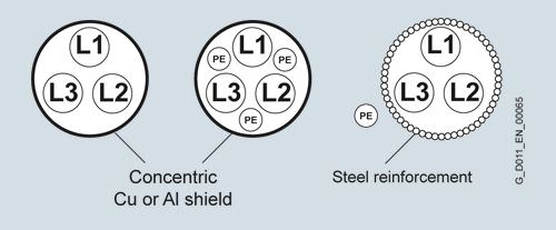
- Use cables with a symmetrical cable cross-section:
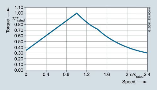
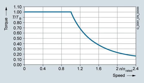
Thermal torque limits (continuous duty)
The thermal torque limit characteristics of the SIMOTICS FD motor series define the maximum load torque for continuous duty (S1) over the complete speed control range. The characteristics are different for all of the cooling methods. The speed control range is limited by the mechanical speed limit, which depends on the motor''s mechanical design.
Thermal torque limit characteristic for the 1LM1 series
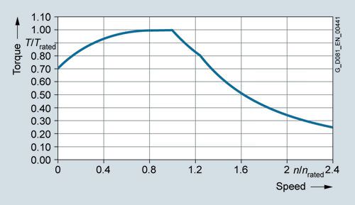
Thermal torque limit characteristic for the 1LL1 series
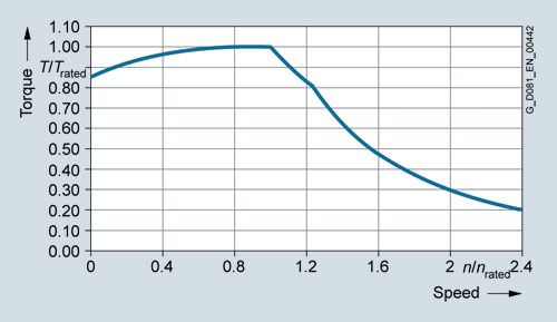
Thermal torque limit characteristic for the 1LQ1 series
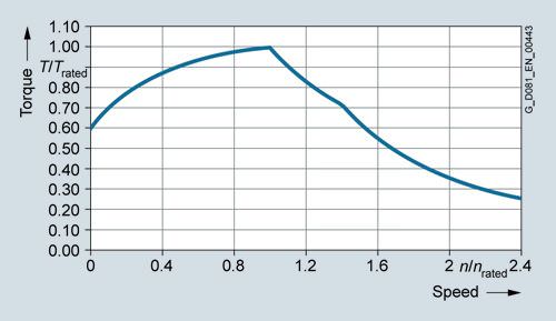
Thermal torque limit characteristic for the 1LP1 and 1LN1 series
Thermal torque limit characteristic for the 1LH1 series
Maximum overload torques
The maximum overload torque output from the motor is defined by the overload torque characteristic over the complete speed control range. The reference variable is the breakdown torque at rated speed. The breakdown torque is calculated from the breakdown torque ratio and the rated torque. Operation at the maximum overload torque is only briefly permissible, for instance, when accelerating. The speed control range is limited by the mechanical speed limit, which depends on the motor''s mechanical design.
SIMOTICS FD overload torque characteristic
More information
Water cooling
- The catalog data for motors with water cooling (1LH1) or with air-to-water heat exchanger (1LN1) are applicable for the following coolant flow rates:
- dV/dt = 40 l/min for the 1LH1 series
- dV/dt = 115 l/min for the 1LN1 series
- dV/dt = 150 l/min for the 1LN1 series (frame size 355)
Mechanical load, grease lifetime
When motors are operated at speeds above the rated speed, the mechanical smooth running operation and the bearings are subjected to greater mechanical stress. This reduces the grease lifetime and the bearing lifetime. More detailed information is available on request. The SIMOTICS FD series optionally has spent grease removal at both bearings.
Motor protection
A motor protection function can be implemented using the I²t sensing circuit implemented in the converter software. If required, more precise motor protection can be afforded by direct temperature measurement using KTY84 sensors (standard scope of delivery), Pt100 resistance thermometers or PTC thermistors in the motor winding. Some converters from Siemens determine the motor temperature using the resistance of the temperature sensor. They can be set to a required temperature for alarm and tripping. If Pt100 resistance thermometers are ordered for winding temperature monitoring (order code A61) or PTC thermistors (order code A12), the standard KTY84 temperature sensors are omitted. A combination of A25 and A61 or A25 and A12 is possible, additional charge on request. KTY or Pt100 sensors are evaluated as described above, e.g. in the converter.
For motors for mains-fed operation, the 3RS10 temperature monitoring device that is part of the protection equipment can be ordered separately. For further details, see Catalog IC 10.
Motor protection is implemented using basic insulation. If protective separation is required, this must be implemented when designing the temperature monitoring system.
Motor connection
When connecting the motors, it is important to consider the restrictions for mains-fed machines as well as the maximum conductor cross-sections permitted for the converter.
Motors specially designed for mains-fed operation (1LH1)
The 1LH1 series also includes motors specifically for mains-fed operation. Contrary to motors specifically for converter-fed operation, it is possible to switch between star and delta connection.
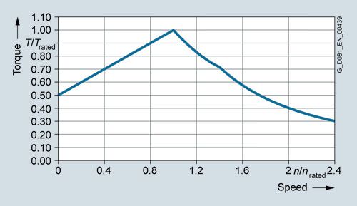
Torque characteristic
The torque generated by a three-phase motor at its shaft variesconsiderably within the speed range n = 0 to n = ns. The characteristic curve of the torque as a function of the speed of a three-phase motor with squirrel-cage rotor is shown in the following diagram.
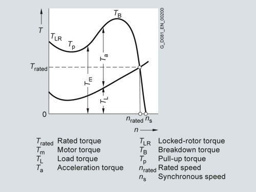
The values for locked-rotor torque and breakdown torque as well as for locked-rotor current for a specific motor can be found in the selection and ordering data.
The limit for the mechanical overload capability is the breakdown torque. According to IEC/EN 60034-1, at rated voltage and at rated frequency, induction motors must have an overload capability of up to 160 % of the rated torque for 15 seconds. If not agreed otherwise, for induction motors, the minimum pull-up torque at rated voltage must have the value specified in the following rated torques.
For three-phase motors without pole changing with a rated output equal to or greater than 100 kW, the following applies:
- 0.3 times rated torque and at least 0.5 times the locked-rotor torque
According to IEC/EN 60034-1, the following tolerances are admissible:
- For locked-rotor torque, from -15 to 25 % of the stated locked-rotor torque
- For locked-rotor current, up to 20 % of the stated locked-rotor current without lower limit
- For the breakdown torque, up to -10 % of the specified breakdown torque
- For pull-up torque, -15 % of the guaranteed value.
Taking these tolerances into account, the locked-rotor torque must be sufficiently higher than the breakaway torque of the driven machine; and the motor torque must constantly exceed the load torque during start-up until the operating speed is achieved.
In the case of squirrel-cage motors, the locked-rotor torque and breakdown torque are listed in the selection and ordering data as multiples of the rated torque.
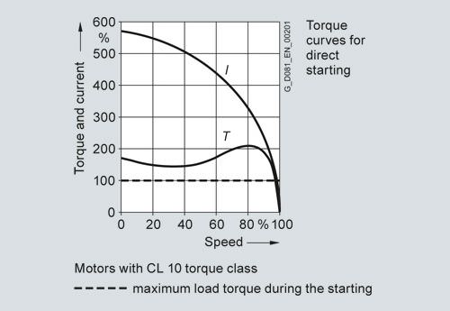
The normal practice is to start squirrel-cage motors directly on line. The torque class indicates that with direct-on-line starting, even if there is an undervoltage of 5 %, it is possible to start up the motor against a load torque of
- 130 % (for CL 13)
- 100 % (for CL 10)
of the rated torque.
The rated torque can be calculated as follows:
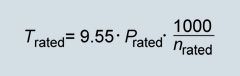
Trated Rated torque in Nm
nrated Rated speed in rpm
Prated Rated output in kW
The rated speed of the motor differs from the synchronous speed by the slip srated
Where:
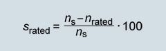
srated Slip in %
nS Synchronous speed in rpm
nrated Rated speed in rpm
Calculation of the start-up time for direct-on-line starting
The start-up time from n = 0 to n = nb can be approximately determined from the average acceleration torque.
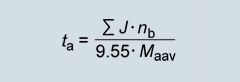
ta Start-up time in s
J Total moment of inertia in kgm2
nb Operating speed in rpm
Taav Average acceleration torque in Nm
The total moment of inertia is made up of the motor moment of inertia plus the moment of inertia of the driven machine and the coupling or belt pulleys and is converted to the speed of the motor shaft.
Limit values for the start-up curve of three-phase squirrel-cage motors for voltages up to and including 690 V are included in IEC/EN 60034.
If problem-free starting is not possible due to a high moment of inertia and/or a high load torque, a larger motor or a three-phase motor with a SINAMICS frequency converter can be used for SIMOTICS FD motors.
A mechanical solution for coping with heavy starting is to use a starting coupling, whose application is limited by its capability to absorb heat.
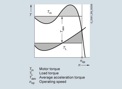
Determination of the average acceleration torque
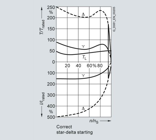
Start-up procedure for three-phase motors with squirrel-cage rotor
Three-phase motors with squirrel-cage rotors should, as far as possible, be started directly on-line.
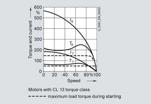
- It should be noted that for any specific motor, the torque and current characteristics are given, independent of the load to be started. Star-delta starting for motors with squirrel-cage rotor is to be used if low locked-rotor currents (e.g. specified by the local power utility) or an especially low starting torque (soft starting) is specified. Locked-rotor torque, breakdown torque and all other torque values as well as the locked-rotor current are 25 to 30 % of the values at direct-on-line starting.
- The motor torque must be sufficiently higher than the load torque during start-up in the star stage. The change from star to delta must not occur before approximately the operating speed.
The first diagram shows a case in which star-delta start-up is not appropriate because the excessive load torque causes the premature switchover which in turn causes a high torque and current surge that renders star-delta starting ineffective.
The torque curve can be approximately reduced by the square of the voltage and the current curve linearly with the voltage by reducing the voltage at the motor terminals with the help of a starting transformer or starting resistors.
Starting at rated current is possible when using a converter (second diagram).
Soft starting for motors with squirrel-cage rotor can also be achieved with short-circuit soft starting or a resistor can be connected in one phase during start-up. The locked-rotor torque can be arbitrarily reduced with the help of this circuit.
The locked-rotor current without a resistor or reactor is slightly higher in both phases than with direct on-line starting.
The electronic SIKOSTART motor starter can be used to better implement starting based on this principle. This device limits the torque and current while starting.
Any inquiries regarding start-up procedures must include the following information:
1. Required output and rated speed of the driven machine
2. Planned motor speed
3. Load torque of the driven machine, depending on the speed of the driven machine or the motor speed
4. Total external moment of inertia and rated speed of the driven machine or referred to the motor speed
5. Number of starts in a specific time period and duty cycle or
6. Characteristics and number of operating cycles in a certain time (method of braking)

Connection and terminal boxes
Terminal box mounting positions
Terminal box position | Fig. on page | Type of construction 1) | |||||||||||||||||||||||
IM B3 | IM B35 | IM B5 with support foot | IM V1 | ||||||||||||||||||||||
Cable entry | |||||||||||||||||||||||||
Right | Left | Top 4) | Bottom | DE | NDE | Right | Left | Top 4) | Bottom | DE | NDE | Right | Left | Top 4) | Bottom | DE | NDE | Right | Left | Top 4) | Bottom | DE | NDE | ||
1LM1, 1LQ1, 1LL1, 1LP1 motors – with IC411, IC416, IC01, IC06 cooling method | |||||||||||||||||||||||||
Version with one terminal box | |||||||||||||||||||||||||
Standard version (DE top) 3) | 1 | ❑ | ✓ | – | – | ✓ | ✓ | ❑ | ✓ | – | – | – | ✓ | ❑ | ✓ | – | – | – | ✓ | – | – | – | – | – | ❑ 5) |
DE right 3) 10) | 2 | – | – | ✓ | – | ✓ | ❑ | – | – | ✓ | – | – | ❑ | – | – | ✓ | ✓ | – | ❑ | – | – | ✓ | ✓ | – | ❑ |
DE left 3) 10) | – | – | ✓ | – | ✓ | ❑ | – | – | ✓ | – | – | ❑ | – | – | ✓ | ✓ | – | ❑ | – | – | ✓ | ✓ | – | ❑ | |
NDE top 6) | 3 | ❑ | ✓ | – | – | ✓ | ✓ | ❑ | ✓ | – | – | ✓ 7) | ✓ | ❑ | ✓ | – | – | ✓ 7) | ✓ | – | – | – | – | ✓ | ❑ |
NDE right 6) 10) | – | – | ✓ | – | ✓ | ❑ | – | – | ✓ | – | ✓ 7) | ❑ | – | – | ✓ | – | ✓ 7) | ❑ | – | – | ✓ | ✓ | ✓ 7) | ❑ | |
NDE left 6) 10) | – | – | ✓ | – | ✓ | ❑ | – | – | ✓ | – | ✓ 7) | ❑ | – | – | ✓ | – | ✓ 7) | ❑ | – | – | ✓ | ✓ | ✓ 7) | ❑ | |
Version with two terminal boxes | |||||||||||||||||||||||||
Both top (NDE and DE) 6) | 4 | ❑ 8) | ✓ 8) | – | – | – | – | ❑ 8) | ✓ 8) | – | – | – | – | ❑ 8) | ✓ 8) | – | – | – | – | – | – | – | – | – | – |
Both left (NDE and DE) 6) 10) | – | – | ❑ 8) | – | – | – | – | – | ❑ 8) | – | – | – | – | – | ❑ 8) | – | – | – | – | – | ❑ 8) | – | – | – | |
Both right (NDE and DE) 6) 10) | – | – | ❑ 8) | – | – | – | – | – | ❑ 8) | – | – | – | – | – | ❑ 8) | – | – | – | – | – | ❑ 8) | – | – | – | |
Both DE (right and left) | – | – | – | – | – | – | – | – | – | – | – | – | – | – | – | – | – | – | – | – | – | – | – | – | |
Both NDE (right and left) | – | – | – | – | – | – | – | – | – | – | – | – | – | – | – | – | – | – | – | – | – | – | – | – | |
1LH1 motors – with IC71W cooling method | |||||||||||||||||||||||||
Version with one terminal box | |||||||||||||||||||||||||
Standard version (DE top) | 2 | ❑ | ✓ | – | – | ✓ 2) | ✓ 2) | ❑ |
Запрос коммерческого предложения× Сообщение отправлено× В ближайшее время сообщение будет обработано. Письмо с номером обращения отправлено на Ваш почтовый ящик. Спасибо за то, что выбрали Первый ZIP! Что-то пошло не так...× К сожалению, наша система расценила Ваше сообщение как спам. Если это произошло по ошибке, пожалуйста, обратитесь к нам по электронной почте. Приносим извинения за возможные неудобства.  Вы отправляете нам запрос  Если у нас есть прайс-лист, мы отправляем Вам ответ в течение дня. А если у нас нет прайс-листа по запрошенным товарам?     Если у нас нет прайс-листа, мы отправляем запрос производителю.  Ответ от производителя может занять до 5 дней и более. Ответ от производителя может занять до 5 дней и более.  Запрос производителю мы отправляем только для конечных потребителей.  Торгующим организациям коммерческие предложения предоставляются только по прайсовым позициям: Siemens Beckhoff Pepperl+Fuchs Phoenix Contact PILZ Turck Leuze Electronic Endress+Hauser Murr Elektronik Schmersal | ||||||||||||||||