Braking resistors Siemens

Обзор

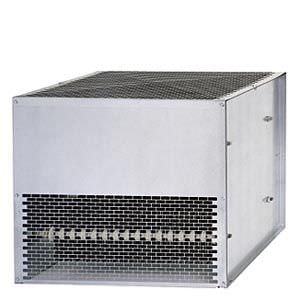
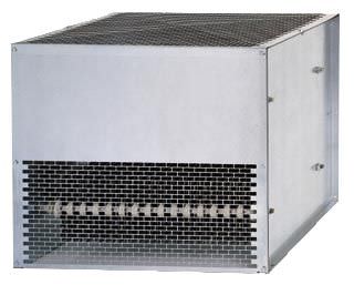
Braking resistor
Excess energy in the DC link is dissipated in the braking resistor.
The braking resistor is connected to the Braking Module. The braking resistor is positioned outside the cabinet or switchgear room. This enables the resulting heat loss to be removed from the area of the Power Modules. The level of air conditioning required is therefore reduced.
A temperature switch (NC contact) is fitted. This responds when the maximum permissible temperature is exceeded and can be evaluated by a controller. The maximum permissible cable length between the Braking Module and braking resistor is 100 m.
Характеристика

Load diagram for Braking Modules and braking resistor
Технические данные
Line voltage 380 V ... 480 V 3 AC | Braking resistor |
|---|---|
| 6SE7032-5FS87-2DC0 |
Resistance | 3.1 Ω (± 10 %) |
Rated power PDB (Continuous braking power) | 50 kW |
Power P20 | 200 kW |
Current, max. | 378 A |
Cable connections | M12 stud |
| 70 mm2 |
| 50 mm2 |
Cable length to Braking Module, max. | ≤100 m |
Degree of protection | IP20 |
Dimensions |
|
| 740 mm |
| 1325 mm |
| 485 mm |
Weight, approx. | 109 kg |
Suitable for Braking Module | 6SL3760-1AE32-6AA0 |


 Ответ от производителя может занять до 5 дней и более.

