TM54F Terminal Module Siemens
Обзор
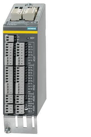
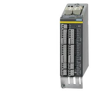
TM54F Terminal Module
The TM54F Terminal Module is a dual-processor I/O interface with four fail-safe digital outputs and ten fail-safe digital inputs for utilization of the Safety Integrated functions of the SINAMICS drive system via external actuators and sensors.
Every available safety function integrated in the drive can be controlled via the fail-safe digital inputs on the TM54F Terminal Module. In the event that the parameterized safety functions of several drives operated together on a Control Unit are to be executed together, then these drives can be grouped in the TM54F Terminal Module. The advantage of this approach is that only one fail-safe digital input needs to be connected for these drives.
The fail-safe digital inputs and outputs have two channels and are redundantly configured with an internal data cross-check using the two processors. A fail-safe digital output consists of one P‑switching and one M‑switching output as well as one digital input to read back the switching state. A fail-safe digital input consists of two digital inputs.
Safety sensors can be connected over two switchable 24 V sensor supplies and can be evaluated over the fail-safe digital inputs. The switchable 24 V sensor supply ensures that the fail-safe digital inputs can be dynamized to detect dormant errors (this dynamization is used to check the shutdown paths). An unswitchable 24 V sensor supply is additionally provided by the TM54F Terminal Module for connecting undynamizable safety sensors.
The TM54F Terminal Module must be directly connected to a Control Unit via a DRIVE‑CLiQ cable. Only one TM54F Terminal Module can be assigned to each Control Unit. It is not permissible to make the TM54F connection via another DRIVE‑CLiQ device, e.g. a Power Module, a Motor Module or a Line Module.
Дизайн
The following are located on the TM54F Terminal Module:
- 4 fail-safe digital outputs
- 10 fail-safe digital inputs
- 4 LEDs, single color for indicating the status of the read back channel of the fail-safe digital outputs
- 4 LEDs, dual-color for indicating the status of the fail-safe digital outputs
- 20 LEDs, dual-color for indicating the status of the fail-safe digital inputs
- 3 LEDs, single color for indicating the status of the 24 V sensor supplies
- 2 DRIVE-CLiQ sockets
- 2 connections for 24 V sensor supply, switchable
- 1 connection for 24 V sensor supply, not switchable
- 1 connection for the electronics power supply via the 24 V DC power supply connector
- 1 connection for the 24 V power supply to digital outputs and sensors
- 1 PE (protective earth) connection
The status of the TM54F Terminal Module is indicated via a multi-color LED.
The TM54F Terminal Module can be snapped onto a TH 35 standard mounting rail according to EN 60715 (IEC 60715).
The signal cable shield can be attached to the TM54F Terminal Module via a shield connection terminal, e.g. type SK8 supplied by Phoenix Contact or type KLBÜ CO 1 supplied by Weidmüller. The shield connection terminal must not be used as a strain relief mechanism.
Pins for connector coding are included in the TM54F Terminal Module scope of supply.
Интеграция
The TM54F Terminal Module can communicate via DRIVE‑CLiQ with the following Control Units.
- CU310‑2 Control Unit
- CU320‑2 Control Unit
- SINUMERIK Control Unit
- SIMOTION D Control Unit or Controller Extension
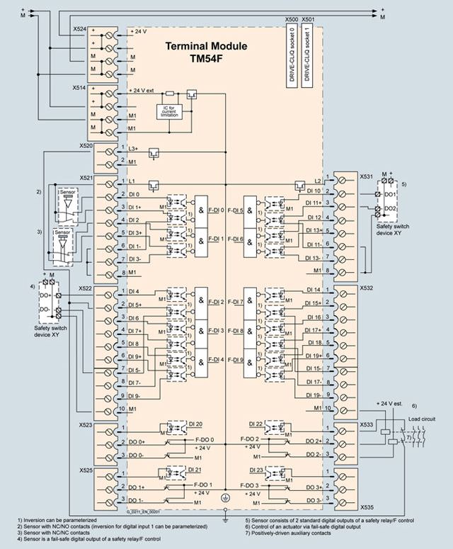
Connection example of TM54F Terminal Module
Технические данные
| TM54F Terminal Module 6SL3055-0AA00-3BA0 |
|---|---|
Current requirement (X524 at 24 V DC) without DRIVE-CLiQ supply | 0.2 A |
| 2.5 mm2 |
| 20 A |
Max. current requirement ext. 24 V for supplying the digital outputs and 24 V sensor supply (X514 at 24 V DC) | 4 A |
| 2.5 mm2 |
| 20 A |
I/O |
|
| 10 |
| 4 |
| 3, of which 2 can be temporarily shut down using an internal test routine for dynamizing fail-safe digital inputs, current carrying capacity 0.5 A each |
| Plug-in screw-type terminals |
| 1.5 mm2 |
Digital inputs in accordance with IEC 61131‑2 Type 1, with galvanic isolation |
|
| -3 ... +30 V |
| -3 ... +5 V |
| 15 ... 30 V |
| > 2 mA |
|
|
| 30 μs |
| 60 μs |
| Low level (for inputs that can be inverted: without inversion) |
Digital outputs (continuously short-circuit proof) |
|
| 24 V DC |
| 0.5 A |
|
|
| 300 μs |
| 350 μs |
| Output switched off |
Scanning cycle tSI for fail-safe digital inputs or fail-safe digital outputs | 4 ... 25 ms (adjustable) |
Power loss, max. At 24 V | 4.5 W |
PE connection | M4 screw |
Dimensions |
|
| 50 mm (1.97 in) |
| 150 mm (5.91 in) |
| 111 mm (4.37 in) |
Weight, approx. | 0.9 kg (2 lb) |
Approvals, according to | cULus |
Safety Integrated | Acc. to IEC 61508 SIL 2 |
1) The specified delay times refer to the hardware. The actual reaction time depends on the time slot in which the digital input/output is processed.
2) The total current of all fail-safe digital outputs must not exceed 5.33 A.


 Ответ от производителя может занять до 5 дней и более.

