SINAMICS S120 drive system Siemens
- Glossary SINAMICS S120 drive system
- CAD CREATOR
- Measuring systems
- Encoder system connection
- Supplementary system components
- SINAMICS S120 Combi
- Blocksize format
- Chassis format
- Control Units
- Booksize format
- Engineering software
- Communication
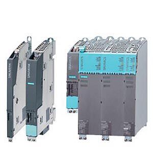
Обзор
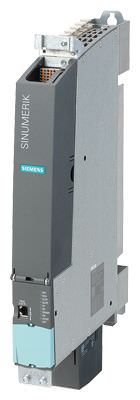

Control Units CU310-2 PN, CU320-2 PN, NCU 730.3 and Numeric Control Extension NX15.3 (from left)
Platform Concept and Totally Integrated Automation
All SINAMICS versions are based on a platform concept. Joint hardware and software components, as well as standardized tools for design, configuration, and commissioning tasks ensure high-level integration across all components.
SINAMICS handles a wide variety of drive tasks with no system gaps. The different SINAMICS versions can be easily combined with each other.
SINAMICS is part of the Siemens "Totally Integrated Automation" concept. Integrated SINAMICS systems covering engineering, data management and communication at automation level, ensure low-effort solutions with the SINUMERIK, SIMOTION, and SIMATIC control systems.
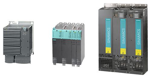
SINAMICS S120 blocksize, booksize, and chassis formats
All formats can be combined freely
The different formats of SINAMICS S120 can be combined freely thanks to their innovative drive architecture with DRIVE-CLiQ interfaces, e.g. Line Modules in chassis format can be freely combined with Motor Modules in booksize format for multi-axis applications with high total output.
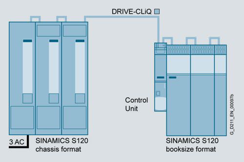
Modular system for demanding drive tasks
SINAMICS S120 solves demanding drive tasks for a wide range of industrial applications and is, therefore, designed as a modular system. Users can choose from many different harmonized components and functions to create a solution that best meets their requirements. The powerful SIZER for Siemens Drives engineering tool makes it easier to choose and determine the optimum drive configuration. This is possible due to the consistent subdivision of the drive in hardware and software function objects, which ensures that the power unit and Control Unit are isolated from each other.
The power units are selected in accordance with the requirements for energy consumption for the motion of the working machine and for exchange of energy with the power supply network. The Control Unit is selected in accordance with the number of drives to be controlled and the performance required.
Communication between the Control Unit and power unit takes place very simply via the digital system interface DRIVE-CLiQ. SINAMICS S120 is enhanced by a wide range of SIMOTICS motors. Whether synchronous or asynchronous, all motor types are supported by SINAMICS S120.
Particularly suitable for multi-axis applications
Coordinated drives that carry out a drive and motion task together are used in many mechanical and plant engineering applications. These require drives with a connected DC link, which allows cost-saving energy balancing between braking and driving axes.
SINAMICS S120 includes Line Modules (line infeed) and Motor Modules (inverters) for a wide performance range. Their format enables a contiguous installation for space-saving multi-axis drive configurations.
System architecture with a central Control Unit
Electronically coordinated single drives work together to perform the drive tasks. Higher-level computerized numerical controls such as SINUMERIK operate the drives to achieve the required coordinated movement. This requires cyclic data exchange between the CNC and all the drives. To solve this task, the SINAMICS S120 uses a central Control Unit that is designed as a higher-level drive controller for all connected axes.
Simple technological tasks can be carried out by the SINAMICS S120 Control Unit itself. For more complex numerical tasks, it is replaced by powerful modules from the SINUMERIK product range.
As well as motion control, coordinate transformation and logic functions, these products also integrate the SINAMICS drive control. The NCUs of SINUMERIK can be positioned in or alongside the SINAMICS S120 drive group and connected via DRIVE-CLiQ. In case of tasks that require a greater number of motion axes due to the machine kinematics, the system base units can be expanded with the additional Numeric Control Extensions NX10.3/NX15.3.
DRIVE-CLiQ – the digital interface between all components
All SINAMICS S120 drive system components, including the motors and encoders, are interconnected by a shared serial interface called DRIVE-CLiQ. The standardized cables and connectors reduce the variety of different parts and cut storage costs.
Sensor Modules (converter boards) for converting standard encoder signals to DRIVE-CLiQ are available for motors and encoders without a DRIVE-CLiQ interface or for retrofitting applications. DRIVE-CLiQ cables are designed to allow decentralized attachments up to 100 m (328 ft).
Swift and automatic: The electronic rating plate
All SINAMICS S120 components with a DRIVE-CLiQ interface have an electronic rating plate. This rating plate contains all the relevant data about that particular component. For motors, for example, these data include the parameters of the electric equivalent circuit diagram and characteristic values for the built-in motor encoder. The Control Unit records this component-specific data automatically via DRIVE-CLiQ so that it does not need to be entered during commissioning or when the equipment is replaced.
In addition to the technical specifications, the rating plate includes logistical data (manufacturer ID, order number, and globally unique ID). Since this data can be called up electronically on site or remotely, all the components used in a machine can always be individually identified, which helps simplify servicing.
The following overview features the SINAMICS S120 components that are primarily used for multi-axis drive tasks.
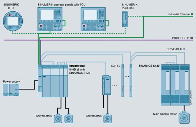
SINAMICS S120 drive system with SINUMERIK 840D sl
Control Units
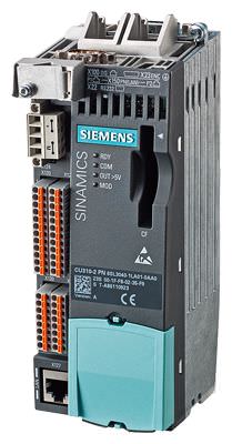
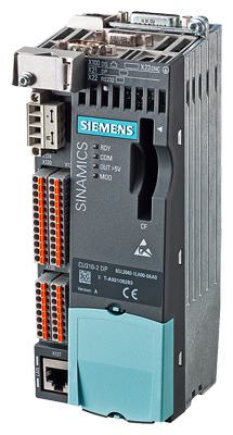
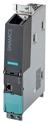
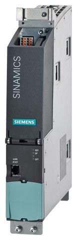


Control Units CU310-2 PN, Control Units CU310-2 DP, CU320-2 PN, CU320-2 DP, NCU 730.3 PN and Numeric Control Extension NX15.3
Control Units for drive control in SINUMERIK, the Numeric Control Extensions NX and the CU320-2
SINAMICS S120 Control Unit CU320-2
These central Control Units can be used to create links between individual drives and implement simple technology functions. The CU320-2 Control Unit has been designed to control multiple drives. With the SINUMERIK, up to 6 drives can be operated in servo control mode on one Control Unit.
The Control Units in the SINUMERIK CNCs are available in various rating classes for implementing coordinated motion control in a multi-axis interpolation grouping on machine tools:
SINUMERIK 840D sl
- NCU 710.3/NCU 720.2/NCU 720.3 PN/NCU 730.2/730.3 PN with integrated drive control for up to 6 axes
- Numeric Control Extensions NX10.3/NX15.3 for extended control of up to 3/6 axes
Commissioning and diagnosis of the various Control Units in combination with the power components is performed in combination with the SINUMERIK using the drive wizard of the SinuCom NC commissioning tool. Alternatively, the drive can be commissioned using the STARTER commissioning tool.
For further information about STARTER, see Engineering software.
Motor Modules
The Motor Modules are the final controlling element for the motor and feature a DC link that is fed from a DC voltage and, as an output, an inverter for feeding the motor.
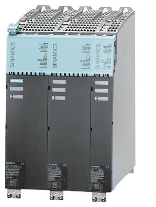
Line Module and two Motor Modules in booksize format

Motor Modules are designed for multi-axis drives and are controlled by a SINUMERIK NCU or a CU320 Control Unit. The Motor Modules are interconnected through a common DC bus. Since the Motor Modules share the same DC link, they can exchange energy with one another, i.e. if one Motor Module operating in generator mode produces energy, the energy can be used by another Motor Module operating in motor mode. The DC link is supplied from the line voltage by a Line Module.
Line Modules
Line Modules generate a DC voltage from the line voltage and supply Motor Modules with energy via the voltage-source DC link. The SINAMICS S120 range contains the following types of Line Modules:
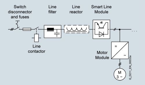
Smart Line Modules
Smart Line Modules can feed energy to the DC link of a drive group through a non-stabilized converter and also feed back the generated excess energy into the power supply system. The line voltage variations are mirrored proportionately in the DC link voltage. Braking Modules and braking resistors are required only if the drives need to be decelerated in a controlled manner for island supply systems or after a power failure (i.e. when energy cannot be recovered to the supply). When a Smart Line Module is used as the infeed, the matching line reactor must be installed. A line filter can be installed optionally to restrict the interference voltage level to EN 61800-3 Class C2 limits.
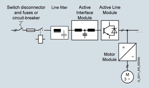
Active Line Modules
Active Line Modules can supply energy to the DC link rail and return regenerative energy to the supply system. In contrast to Smart Line Modules, Active Line Modules generate a regulated DC voltage which remains constant despite fluctuations in the line voltage. In this case, the line voltage must remain within the permissible tolerance range. Braking Modules and braking resistors are required only if the drives need to be decelerated in a controlled manner even after a power failure (when energy cannot be recovered to the supply). Active Line Modules draw a virtually sinusoidal current from the supply which virtually rules out any harmful harmonics. It is essential that the Active Interface Module matched to the output type is used (block diagram, see Active Line Modules in chassis format).
Active Line Modules in chassis format
All the components required to operate an Active Line Module are integrated in the Active Interface Module. An external bypass contactor is required in addition for sizes HX and JX.
Power Modules
The simplest version of a SINAMICS S120 drive system consists of a CU310 DP Control Unit and a Power Module. A mains rectifier, a voltage-source DC link and an inverter for supplying a motor are integrated in the Power Module.

Power Module in blocksize format with CU310-2 DP Control Unit

Power Modules can also be operated by a CU320-2 Control Unit or a drive control integrated in SINUMERIK, e.g. in configurations where a single drive has been added to a multi-axis drive group. In this case, the Power Modules in blocksize format must be equipped with the CUA31 Control Unit Adapter. This is connected with the CU320-2 Control Unit or the NCU in SINUMERIK using DRIVE-CLiQ. Power Modules in chassis format are directly connected to the Control Unit using a DRIVE-CLiQ cable.
The following versions are available:
- Motor Modules and Line Modules in booksize and chassis formats
- Power Modules in blocksize and chassis formats
- Motor Modules in booksize compact format
- SINAMICS S120 Combi
Booksize format
Booksize format units are optimized for multi-axis applications and are mounted adjacent to one another. The connection for the common DC link is an integral feature.

With respect to control cabinet cooling, SINAMICS S120 in booksize format offers a number of highly effective options. Depending on the application, component heat loss can be transferred to the environment using three different heat dissipation methods. The design of the components differs only in the format of the backplane and the location of the external fan module. The front panel (where the connections are located) and the width of the components are common to all designs.
Internal air cooling
In this standard solution, the power loss from the electronics and power units of the drive components is removed by natural cooling or by a forced-ventilation system and routed to the interior of the control cabinet.
External air cooling
External air cooling uses the through-hole technology. The components'' power unit heat sinks pass through the mounting surface in the control cabinet and can thus dissipate the heat losses of the power circuit to a separate external cooling circuit. Degree of protection IP54 can be achieved at this "mechanical interface" – the external heat sink. The heat sink, with its cooling fins and the fan module (part of the scope of supply), protrudes through the back into a separate ventilation duct, which can also be open to the outside. The only heat loss that remains in the cabinet is largely emitted by the electronics.
Chassis format
Higher-output units (approximately 100 kW and above) are constructed in chassis format. These devices are available as Line Modules and Motor Modules. Chassis format units are cooled by an internal air cooling circuit.

Blocksize format
The units in blocksize format are optimized for single-axis applications.
The CU310-2 DP/CU310-2 PN Control Units or CUA31 Control Unit Adapters can be snapped on directly. The units are cooled by an internal air cooling circuit.
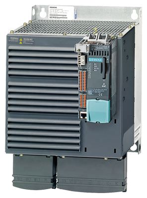
Power Module with CU310-2 PN Control Unit plugged in
SINAMICS S120 Combi
SINAMICS S120 Combi is a very compact and rugged drive system for compact turning and milling machines.
The prerequisite for operation of the SINMAICS S120 Combi is a NCU 710.3 PN.
SINAMICS S120 Combi integrates a line infeed with regenerative feedback capability, power units for spindle and feed motors as well as a TTL encoder interface into a single Power Module.
Special features are the minimum space requirement in the control cabinet, low energy requirement thanks to state-of-the-art 400-V technology, and perfected expendability using additional Motor Modules in booksize compact format.
The expansion using Motor Modules in booksize compact format is only permissible in combination with a NCU 710.3 PN and the SINAMICS S120 Combi (SINUMERIK 840D sl BASIC).
An intelligent DRIVE-CLiQ interface is provided for cabling.
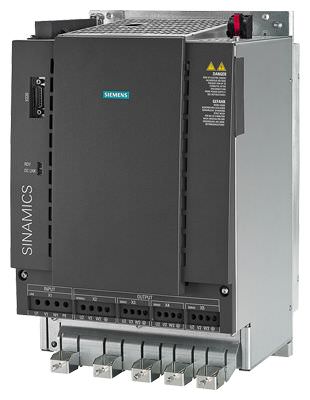
SINAMICS S120 Combi
Additional system components
The structure of the drive system is defined by the selected Control Unit, Line Module, and Motor Modules or Power Module. An optimal solution can be obtained for the drive task using these system components.
Additional system components can be installed to expand the system''s scope of functions and adapt it perfectly to the drive task in question.
System components are divided into the following categories:
- DC link components
e.g. Braking Modules and braking resistors
Further DC link components are optionally installed to stabilize the DC link voltage and/or to support the electronics power supply. - Additional system components
e.g. Terminal Modules for expanding the I/O interfaces to the machine interface - Encoder system connection
for connecting various types of encoders to SINAMICS S120 - Line-side power components
such as fuses, contactors, reactors, and filters for switching the power supply and meeting EMC requirements
Energy efficiency
The SINAMICS S120 drive system saves energy by recovering energy from the axes and using it within the DC link group of a multi-axis configuration and by feeding it back into the supply system. Even at full infeed capacity, no unnecessary heat is generated in the control cabinet. With intelligent compensation of capacitive and inductive reactive currents, SINAMICS S120 also ensures that no unnecessary power losses occur in the power supply and that no current harmonics occur. This not only prevents detrimental effects on other loads, but it also reduces the heat generated in the control cabinet.
The SINAMICS S120 components have been developed for installation in cabinets
They have the following features and characteristics:
- Ease of handling
- Simple assembly and wiring
- Practical connection system, cable routing in accordance with EMC requirements
- Uniform design
- Contiguous assembly
- Various cooling solutions
Rugged units
The SINAMICS units are equipped as standard with varnished or partially varnished modules for enhanced robustness.
The coating on the modules protects the sensitive SMD components against corrosive gases, chemically active dust and moisture.
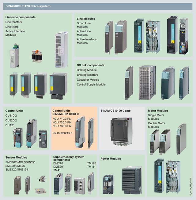
SINUMERIK and SINAMICS automation system components
Технические данные
Unless specified otherwise, the following technical specifications are valid for all the following components of the SINAMICS S120 drive system.
Drive system | SINAMICS S120 |
Electronics power supply | 24 V DC, -15%/+20% |
Vibratory load |
|
|
|
| Class 2M3 |
| Class 2M2 |
| |
| 10 ... 58 Hz: Constant deflection, 0.075 mm (0.003 in) 58 ... 150 Hz: Constant acceleration = 9.81 m/s2 (3.2 ft/s2) (1 × g) |
Shock load |
|
|
|
| Class 2M3 |
| Class 2M2 |
| |
| 147 m/s2 (482 ft/s2) (15 × g)/11 ms |
| 49 m/s2 (161 ft/s2) (5 × g)/30 ms |
| 98 m/s2 (321 ft/s2) (10 × g)/20 ms |
Ambient conditions |
|
| Class I (with protective conductor system) and Class III (PELV) |
| DIN VDE 0106 Part 100 and BGV A 3 when used properly |
| Internal/external air cooling, power units with increased air cooling by means of built-in fan |
Permissible ambient/coolant temperature (air) during operation |
|
| 0 ... 40 °C (32 ... 104 °F) without derating, |
| 0 … 55 °C (32 … 131 °F) |
Climatic ambient conditions |
|
| Class 1K4 |
| Class 2K4 |
| Class 3K3 |
Environmental class/harmful chemical substances |
|
| Class 1C2 |
| Class 2C2 |
| Class 3C2 |
Organic/biological influences |
|
| Class 1B1 |
| Class 2B1 |
| Class 3B1 |
Degree of contamination According to EN 61800‑5‑1 | 2 |
1) In transport packaging.
European standards | |
|---|---|
EN 954‑1 | Safety of machinery – Safety-related parts of control systems |
EN 61508‑1 | Functional safety of electrical/electronic/programmable electronic safety-related systems |
EN 50370‑1 | Electromagnetic compatibility (EMC) – Product family standard for machine tools |
EN 55011 | Industrial, scientific and medical high-frequency equipment (ISM devices) – Radio-frequency disturbance characteristics – Limits and methods of measurement |
EN 60204‑1 | Electrical equipment of machines |
EN 61800‑3 | Adjustable speed electrical power drive systems |
EN 61800‑5‑1 | Adjustable speed electrical power drive systems |
North American standards | |
UL508C | Power conversion equipment |
CSA C22.2 No. 14 | Industrial control equipment |
Approvals | |
cULus1) | Testing by UL (Underwriters Laboratories) according to UL and CSA standards |
Дальнейшая информация
For satisfactory and reliable operation of the drive system, original components of the SINAMICS system in conjunction with the original Siemens accessories as described in this Catalog and the Configuration Manuals, in the functional descriptions or user manuals should be used.
The user must observe the configuring instructions.
Combinations that differ from the configuring instructions (also in conjunction with non-Siemens products) require a special agreement.
If no original components are used, for example for repairs, approvals such as UL, EN, Safety Integrated, etc. can become invalid and thus the operation authorization for the machine with the non-Siemens components installed becomes invalid.
All of the approvals, certificates, declarations of conformity, test certificates, e.g. CE, UL, Safety Integrated etc. have been performed with the associated system components as they are described in the Catalogs and Configuration Manuals. The certificates are only valid if the products are used with the described system components, are installed according to the Installation Guidelines and are used for their intended purpose. In other cases, the vendor of these products is responsible for arranging that new certificates are issued.


 Ответ от производителя может занять до 5 дней и более.

