CU320-2 Control Unit Siemens

Обзор
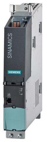
The communication, open-loop and closed-loop control functions for one or more Motor Modules and the Line Module are executed in a CU320‑2 Control Unit. The CU320‑2 Control Unit is essentially designed for multi-axis operation.
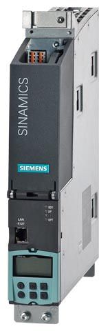
CU320‑2 DP Control Unit with BOP20 Basic Operator Panel
CompactFlash card for CU320‑2 Control Units
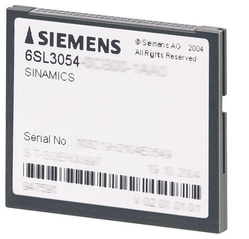
The CompactFlash card contains the firmware and parameter settings. The CompactFlash card is plugged into the appropriate slot on the CU320‑2 Control Unit.
A CU320‑2 Control Unit can perform the communication, open-loop and closed-loop control functions for several Motor Modules. The computing capacity required increases in proportion to the number of connected Motor Modules and system components and in relation to the dynamic response required. For the CU320‑2 Control Unit, the performance expansion is necessary from the 4th axis. The utilization of the CU320‑2 Control Unit can be calculated with the SIZER engineering tool.
In addition to the firmware, the CompactFlash Card also contains licensing codes which are required to enable firmware options.
In addition to the Article No., the following firmware options can currently be ordered with or without performance expansion:
- Safety Integrated Extended Functions, order codes per axis F01 to F06(see chapter Safety Integrated)
- High output frequency 1), order code J01
- DCB Extension, order code U01
The firmware options can also be enabled on-site, for example, if the performance expansions required are not known at the time of placing the order or the Safety Integrated Extended Functions are to be enabled retrospectively. You will need the serial number of the CompactFlash card and the Article No. of the firmware option to be enabled. With this information, you can purchase the associated license code from a license database and enable the firmware option. The license code is only valid for the CompactFlash card declared and cannot be transferred to other CompactFlash cards.
1) For further information see http://support.automation.siemens.com/WW/view/en/104020669
Дизайн
CU320‑2 Control Units feature the following interfaces as standard:
- 4 DRIVE‑CLiQ sockets for communication with other DRIVE‑CLiQ nodes, e.g. Motor Modules, Active Line Modules, Sensor Modules, Terminal Modules
- CU320‑2 PN: 1 PROFINET interface with 2 ports (RJ45 sockets) with PROFIdrive V4 profile
- CU320‑2 DP: 1 PROFIBUS interface with PROFIdrive V4 profile
- 12 parameterizable digital inputs (floating)
- 8 parameterizable bidirectional digital inputs/outputs (non-floating)
- 1 serial RS232 interface
- 1 interface for the BOP20 Basic Operator Panel
- 1 slot for the CompactFlash card on which firmware and parameters are stored
- 1 slot for mounting an option module (e.g. TB30 Terminal Board)
- 2 rotary coding switches for manually setting the PROFIBUS address
- 1 Ethernet interface for commissioning and diagnostics
- 3 test sockets and one reference ground for commissioning support
- 1 connection for the electronics power supply via the 24 V DC supply connector
- 1 PE/protective conductor connection
- 1 ground connection
A shield connection for the signal cable shield on the option module is located on the CU320‑2 Control Unit.
The available option slot is used to expand the interfaces, for example, to include additional terminals or for communication purposes.
The status of the CU320‑2 Control Unit is indicated via multi-color LEDs.
As the firmware and parameter settings are stored on a plug-in CompactFlash card, the Control Unit can be changed without the need for software tools.
The CU320‑2 Control Unit can be mounted on the side of the Line Module in booksize format via brackets integrated in a Line Module. The CU320‑2 Control Unit can also be fixed to the wall of the control cabinet using the integrated fixing lugs. As the CU320‑2 Control Unit is not as deep as the Line Modules, suitable spacers are available to increase the depth of the CU320‑2 Control Unit to 270 mm (10.63 in).
Интеграция
DRIVE‑CLiQ components such as Motor Modules and Active Line Modules can be connected to a CU320‑2 Control Unit. The number of modules depends on the performance required, including duty type and additional functions.
The BOP20 Basic Operator Panel can also be snapped onto the CU320‑2 Control Unit during operation to perform diagnostics.
The CU320‑2 Control Unit and other connected components are commissioned and diagnosed with the STARTER commissioning tool.
A CompactFlash card with firmware version V4.4 or higher is a mandatory requirement for operation of the CU320‑2 PN Control Unit.
A CompactFlash card with firmware version V4.3 or higher is a mandatory requirement for operation of the CU320‑2 DP Control Unit.
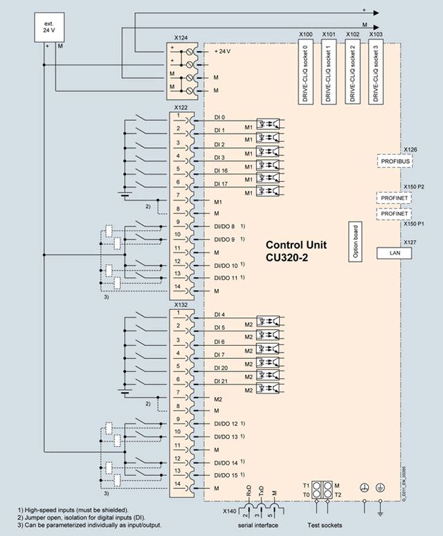
Connection example of a CU320‑2 Control Unit
Технические данные
PROFINET | CU320‑2 Control Unit 6SL3040-1MA01-0AA0 |
|---|---|
Power requirement, max. At 24 V DC, | 1.0 A |
Conductor cross-section, max. | 2.5 mm2 |
Fuse protection, max. | 20 A |
Digital inputs | In accordance with IEC 61131‑2 Type 1 12 isolated digital inputs 8 bidirectional non-isolated digital inputs/digital outputs |
| -3 ... +30 V |
| -3 ... +5 V |
| 15 ... 30 V |
| 9 mA |
|
|
| 5 μs |
| 50 μs |
| 1.5 mm2 |
Digital outputs Sustained short-circuit strength | 8 bidirectional non-isolated digital inputs/digital outputs |
| 24 V DC |
| 500 mA |
|
|
| 150 μs/400 μs |
| 75 μs/100 μs |
| 1.5 mm2 |
Power loss | 24 W |
PE connection | M5 screw |
Ground connection | M5 screw |
Dimensions |
|
| 50 mm (1.97 in) |
| 300 mm (11.81 in) |
| 226 mm (8.90 in) |
Weight, approx. | 2.3 kg (4.5 lb) |
Approvals, according to | cULus |
1) The specified delay times refer to the hardware. The actual reaction time depends on the time slot in which the digital input or output is processed.


 Ответ от производителя может занять до 5 дней и более.

