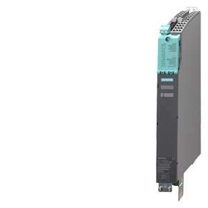
Smart Line Modules in booksize format Siemens
Обзор
Smart Line Modules are non-regulated, line-commutated feed/feedback units (diode bridge for incoming supply; linecommutated feedback via IGBTs) with 100 % continuous regenerative feedback power. The regenerative feedback capability of the modules can be deactivated by means of a digital input (Smart Line Modules 5 kW and 10 kW) or by means of parameterization (Smart Line Modules 16 kW, 36 kW and 55 kW). Smart Line Modules are designed for connection to grounded TN/TT and non-grounded IT systems.
The DC link is pre-charged via integrated pre-charging resistors.
The associated line reactor is absolutely essential for operating a Smart Line Module.
Дизайн
Smart Line Modules in booksize format feature the following connections and interfaces as standard:
- 1 power connection via screw-type terminals
- 1 connection for the 24 V DC electronics power supply via the24 V terminal adapter included in the scope of supply
- 1 DC link connection via integrated DC link busbars
- 2 PE (protective earth) connections
- 2 digital inputs
(only on 5 kW and 10 kW Smart Line Modules) - 1 digital output
(only on 5 kW and 10 kW Smart Line Modules) - 3 DRIVE‑CLiQ sockets
(only on 16 kW, 36 kW and 55 kW Smart Line Modules)
The status of the Smart Line Modules is indicated via two multi-color LEDs.
The signal cable shield can be connected to the Line Module by means of a shield connection terminal, e.g. Weidmüller type KLBÜ 3‑8 SC.
The scope of supply of the Smart Line Modules includes:
- DRIVE‑CLiQ cable for connection to the adjacent Control Unit on the left for drive control, length 0.11 m (4.33 in)
(on 16 kW, 36 kW and 55 kW Smart Line Modules only) - 2 blanking plugs for sealing unused DRIVE‑CLiQ sockets
(on 16 kW, 36 kW and 55 kW Smart Line Modules only) - DRIVE‑CLiQ cable (length depends on module width) to connect Smart Line Module to adjacent Motor Module, length = width of Smart Line Module + 0.11 m (4.33 in)
- Jumper for connecting the 24 V DC busbar to the adjacent Motor Module
- 24 V terminal adapter (X24)
- Connector X21 for digital inputs and outputs
- Connector X22 for digital inputs and outputs
(on 5 kW and 10 kW Smart Line Modules only) - Connector X1 for line supply connection
(on 5 kW and 10 kW Smart Line Modules only) - 1 set of warning signs in 30 languages
- 1 heat conducting foil
(for Smart Line Modules with cold plate cooling only)
Характеристика
Overload capability
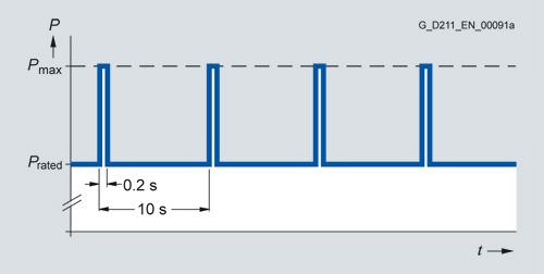
Load cycle with previous load
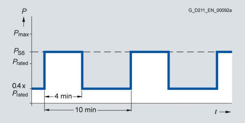
S6 load cycle with previous load
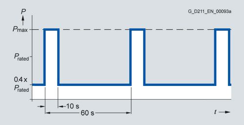
S6 load cycle with previous load
Derating characteristics
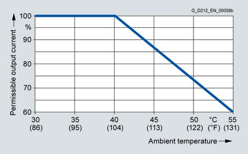
Output power dependent on ambient temperature
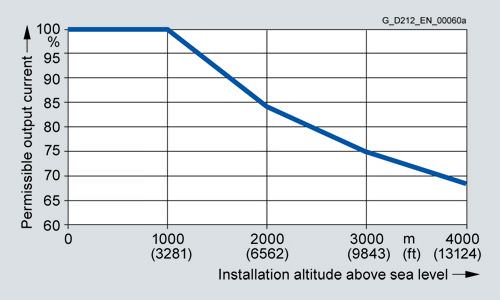
Output power dependent on installation altitude
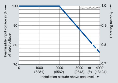
Voltage derating dependent on installation altitude
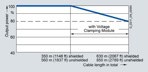
Output power dependent on total cable length
Интеграция
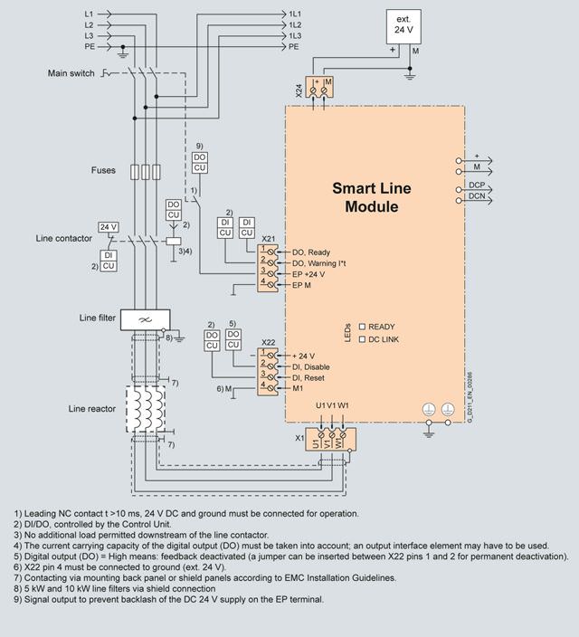
Connection example of 5 kW and 10 kW Smart Line Modules in booksize format
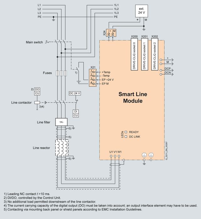
Connection example of 16 kW, 36 kW and 55 kW Smart Line Modules in booksize format
Технические данные
Smart Line Module in booksize format 6SL313... |
|
|---|---|
Line voltage (up to 2000 m (6562 ft) above sea level) | 380 ... 480 V 3 AC ±10 % (in operation -15 % <1 min) |
Line frequency | 47 ... 63 Hz |
SCCR (short-circuit current rating) | 65 kA in conjunction with the recommended fuses class J or circuit breakers in accordance with UL489 / CSA 22.2 No. 5-02 see recommended line-side components |
Line power factor at rated power |
|
| >0.96 |
| 0.65 ... 0.9 |
Overvoltage category according to EN 60664‑1 | Class III |
DC link voltage, approx. | 1.35 x line voltage1) |
Electronics power supply | 24 V DC, -15 %/+20 % |
Radio interference suppression |
|
| No radio interference suppression |
| Category C2 to EN 61800‑3 |
Type of cooling | Internal air cooling External air cooling, power units with increased air cooling by built-in fan Cold-plate cooling (5 kW and 10 kW) |
Permissible ambient and coolant temperature (air) during operation for line-side components, Line Modules and Motor Modules | 0 ... 40 °C (32 ... 104 °F) without derating, |
Installation altitude | Up to 1000 m (3281 ft) above sea level without derating, |
Declarations of conformity | CE (Low-Voltage and EMC Directives) |
Approvals, according to | cULus |
1) The DC link voltage is regulated to the mean value of the rectified line voltage.For more information, see chapter System description - Dimensioning.
Line voltage 380 ... 480 V 3 AC | Smart Line Module in booksize format | |||||
|---|---|---|---|---|---|---|
Internal air cooling | 6SL3130-... | 6AE15-0AB1 | 6AE21-0AB1 | 6TE21-6AA4 | 6TE23-6AA3 | 6TE25-5AA3 |
External air cooling | 6SL3131-... | 6AE15-0AA1 | 6AE21-0AA1 | 6TE21-6AA3 | 6TE23-6AA3 | 6TE25-5AA3 |
Cold plate cooling | 6SL3136-... | 6AE15-0AA1 | 6AE21-0AA1 | – | – | – |
Infeed/regenerative feedback power |
|
|
|
|
|
|
| ||||||
| kW | 5 | 10 | 16 | 36 | 55 |
| (HP) | (5) | (10) | (18) | (40) | (60) |
| kW | 6.5 | 13 | 21 | 47 | 71 |
| kW | 10 | 20 | 35 | 70 | 91 |
DC link current |
|
|
|
|
|
|
| A | 9.3/8.3 | 18.5/16.6 | 30/27 | 67/60 | 105/92 |
| A | 11 | 22 | 35 | 79 | 138 |
| A | 16.6 | 33.2 | 59 | 117 | 178 |
Input current |
|
|
|
|
|
|
| A | 8.6/8.1/6.7 | 17/16.2/12.8 | 26/25/21 | 58/55/46 | 94/90/77 |
| A | 10.6 | 21.1 | 33 | 72 | 106 |
| A | 15.7 | 31.2 | 54 | 107 | 130 |
Power requirement 24 V DC electronics power supply, max. | A | 0.8 | 0.9 | 0.95 | 1.5 | 1.9 |
Current carrying capacity |
|
|
|
|
|
|
| A | 20 | 20 | 20 | 20 | 20 |
| A | 100 | 100 | 100 | 200 | 200 |
DC link capacitance |
|
|
|
|
|
|
| μF | 220 | 330 | 710 | 1410 | 1880 |
| μF | 6000 | 6000 | 20000 | 20000 | 20000 |
Internal/external air cooling |
|
|
|
|
|
|
|
|
|
|
|
|
|
| kW | 0.08 | 0.14 | 0.19 | 0.405 | 0.665 |
| kW | 0.04/0.04/0.08 | 0.065/0.075/0.14 | 0.065/0.125/0.19 | 0.115/0.29/0.405 | 0.185/0.48/0.665 |
| m3/s (ft3/s) | 0.008 (0.3) | 0.008 (0.3) | 0.016 (0.6) | 0.031 (1.1) | 0.044 (1.5) |
| dB | <60 | <60 | <60 | <60 | <60 |
Cold plate cooling |
|
|
|
|
|
|
| kW | 0.035/0.04 | 0.055/0.08 | – | – | – |
| K/W | 0.175 | 0.175 | – | – | – |
Line connection U1, V1, W1 |
| Screw-type terminals (X1) | Screw-type terminals (X1) | Screw-type terminals (X1) | M6 screw studs (X1) | M6 screw studs (X1) |
| mm2 | 2.5 ... 6 | 2.5 ... 6 | 2.5 ... 10 | 2.5 ... 50 | 2.5 ... 95 |
Shield connection |
| Shield connection plate integrated into the connector | Shield connection plate integrated into the connector | Shield connection plate integrated into the connector | See Accessories | See Accessories |
PE connection |
| M5 screw | M5 screw | M5 screw | M6 screw | M6 screw |
Cable length, max. (total of all motor power cables |
|
|
|
|
|
|
| m (ft) | 350 (1148) | 350 (1148) | 350 (1148) | 350 (1148) | 350 (1148) |
| m (ft) | 560 (1837) | 560 (1837) | 560 (1837) | 560 (1837) | 560 (1837) |
Degree of protection |
| IP20 | IP20 | IP20 | IP20 | IP20 |
Dimensions |
|
|
|
|
|
|
| mm (in) | 50 (1.97) | 50 (1.97) | 100 (3.94) | 150 (5.91) | 200 (7.87) |
| mm (in) | 380 (14.96) | 380 (14.96) | 380 (14.96) | 380 (14.96) | 380 (14.96) |
|
|
|
|
|
|
|
| mm (in) | 270 (10.63) | 270 (10.63) | 270 (10.63) | 270 (10.63) | 270 (10.63) |
| mm (in) | 226/66.5 (8.90/2.62) | 226/66.5 (8.90/2.62) | 226/66.5 (8.90/2.62) | 226/71 (8.90/2.80) | 226/92 (8.90/3.62) |
| mm (in) | 226 (8.90) | 226 (8.90) | – | – | – |
Weight, approx. |
|
|
|
|
|
|
| kg (lb) | 4.7 (10.4) | 4.8 (10.6) | 7 (15.4) | 10.3 (22.7) | 17 (37.5) |
| kg (lb) | 5.3 (11.7) | 5.4 (11.9) | 8.8 (19.4) | 13.8 (30.4) | 18.5 (40.8) |
| kg (lb) | 4 (8.82) | 4 (8.82) | – | – | – |
1) Power loss of Smart Line Module at rated power including losses of 24 V DC electronics power supply.
2) Power loss of the power electronics + power loss of the 24 V electronics
3) Nominal HP ratings are provided for ease of assigning components only. The Line Module outputs are dependent on the Motor Module loading and are to be dimensioned accordingly.


 Ответ от производителя может занять до 5 дней и более.

