Active Interface Modules Siemens

Обзор
Active Interface Modules for 16 kW, 36 kW, 55 kW and 80 kW/120 kW
The Active Interface Modules combine with the Active Line Modules to form a functional unit and are essential for operation of the associated Active Line Module. The Active Interface Modules contain a Clean Power Filter, reactor, and basic interference suppression to ensure compliance with Category C3 in accordance with EN 61800‑3 regarding emitted interference.
The Clean Power Filter protects the line supply from switching-frequency harmonics. The drive system therefore draws a sinusoidal current from the supply and causes virtually no harmonics.
The Active Line Modules in combination with the Active Interface Module can also be operated with supply systems with an isolated star point (IT systems).
Дизайн
The scope of supply of the Active Interface Modules includes:
- Connector X21 for temperature evaluation and fan control
- Connector X24 for connecting the 24 V supply for the integrated fan
- DRIVE‑CLiQ cable for connecting the Control Unit to the Active Line Module; length of the DRIVE‑CLiQ cable = width of the Active Interface Module + 0.11 m (4.33 in)
- Shield connection plate for Active Interface Module 16 kW
- 1 set of warning signs in 30 languages
Характеристика
Overload capability
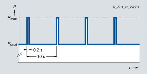
Load cycle with previous load
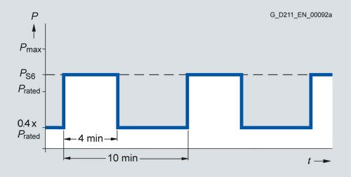
S6 load cycle with previous load
S6 load cycle with previous load
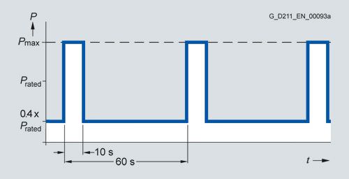
55 kW Active Line Module only:
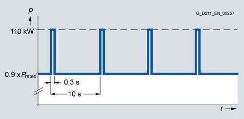
Peak power load duty cycle with previous load
Derating characteristics
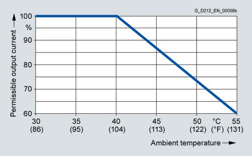
Output power dependent on ambient temperature
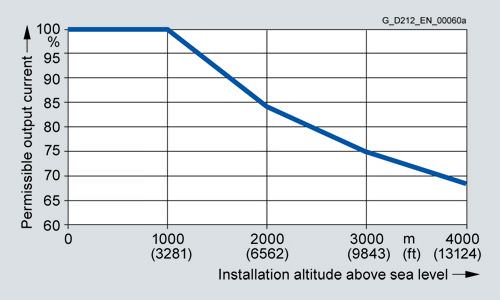
Output power dependent on installation altitude
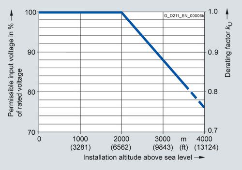
Voltage derating dependent on installation altitude
Интеграция
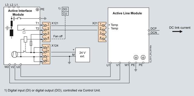
Connection example for Active Interface Module
The Active Interface Module requires a 24 V DC supply for operation of the integral fan.
The fan rotates after the 24 V DC supply is applied and can, if necessary (service life, noise), be shut off fom the Control Unit over the "Fan off" input. It is only permitted to switch off the fan when the infeed of the drive system is not operating, otherwise the Active Interface Module will overheat.
The thermostatic switch installed in the Active Interface Module is evaluated over the connected Active Line Module.
The power cables between the Active Interface Module and Active Line Module must be shielded if limit values for interference suppression are to be complied with. The cable shield can be routed over the shield connection plate (option) to the Active Interface Module or Active Line Module.
Depending on the position of the Active Interface Module in the drive system, additional DRIVE‑CLiQ cables may be required. If it is separately installed next to the left side of the Control Unit and Active Line Module, no additional DRIVE‑CLiQ cables are required. If the Active Interface Module is placed between the Control Unit and Active Line Module, the DRIVE‑CLiQ cables supplied with the Active Line Modules are suitable for setting up a line topology, i.e. Active Line Module and all Motor Modules in series on one DRIVE‑CLiQ line. If the Active Line Module is connected over a separate DRIVE‑CLiQ line, the DRIVE‑CLiQ cable marked with (1) must be ordered. A DRIVE‑CLiQ cable suitable for connection (2) is included in the scope of supply of the Active Line Module.
For DRIVE‑CLiQ cables for different configurations, see chapter MOTION‑CONNECT connection systems).
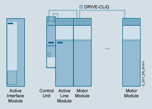
Separate Active Interface Module
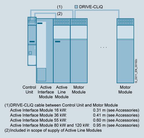
Active Interface Module integrated in the drive line-up
Технические данные
Line voltage 380 ... 480 V 3 AC | Active Interface Module | |||||
|---|---|---|---|---|---|---|
Internal air cooling | 6SL3100-0BE21-6AB0 | 6SL3100-0BE23-6AB0 | 6SL3100-0BE25-5AB0 | 6SL3100-0BE28-0AB0 | 6SL3100-0BE31-2AB0 | |
Rated current | A | 27 | 60 | 88 | 132 | 200 |
Power requirement 24 V DC electronics power supply, max. | A | 0.25 | 0.5 | 0.6 | 1.2 | 1.2 |
Internal resistance Digital input | Ω | 1440 ±10 % | 1440 ±10 % | 1440 ±10 % | 1440 ±10 % | 1440 ±10 % |
Power loss | kW | 0.3 | 0.39 | 0.45 | 0.575 | 0.8 |
Cooling air requirement | m3/s (ft3/s) | 0.03 (1.1) | 0.04 (1.4) | 0.075 (2.6) | 0.15 (5.3) | 0.15 (5.3) |
Sound pressure level LpA (1 m) | dB | 57 | 60 | 66 | 68 | 68 |
Line/load connection L1, L2, L3/U2, V2, W2 |
| Screw-type terminals | Screw-type terminals | Screw-type terminals | M8 screw studs | M8 screw studs |
| mm2 | 16 | 50 | 50 | 2.5 … 120 or 2 × 50 | 2.5 … 120 or 2 × 50 |
Thermostatic switch (NC contact) |
|
|
|
|
|
|
|
| 250 V AC/1.6 A | 250 V AC/1.6 A | 250 V AC/1.6 A | 250 V AC/1.6 A | 250 V AC/1.6 A |
PE connection |
| M5 screw | M5 screw | M6 screw | M8 screw | M8 screw |
Degree of protection |
| IP20 | IP20 | IP20 | IP20 | IP20 |
Dimensions |
|
|
|
|
|
|
| mm (in) | 100 (3.94) | 150 (5.91) | 200 (7.87) | 300 (11.81) | 300 (11.81) |
| mm (in) | 380 (14.96) | 380 (14.96) | 380 (14.96) | 380 (14.96) | 380 (14.96) |
| mm (in) | 270 (10.63) | 270 (10.63) | 270 (10.63) | 270 (10.63) | 270 (10.63) |
Weight, approx. | kg (lb) | 11 (24.3) | 18.5 (40.8) | 21 (46.3) | 29 (64.0) | 36 (79.4) |
Approvals, according to |
| cURus | cURus | cURus | cURus | cURus |
Suitable for Active Line Module in booksize format | Type | 6SL3130-7TE21-6AA4 6SL3131-7TE21-6AA3 6SL3136-7TE21-6AA3 | 6SL3130-7TE23-6AA3 6SL3131-7TE23-6AA3 6SL3136-7TE23-6AA3 | 6SL3130-7TE25-5AA3 6SL3131-7TE25-5AA3 6SL3136-7TE25-5AA3 | 6SL3130-7TE28-0AA3 6SL3131-7TE28-0AA3 6SL3136-7TE28-0AA3 | 6SL3130-7TE31-2AA3 6SL3131-7TE31-2AA3 6SL3136-7TE31-2AA3 6SL3135-7TE31-2AA3 |
| kW | 16 | 36 | 55 | 80 | 120 |


 Ответ от производителя может занять до 5 дней и более.

